
- Home
- Capabilities
- Solution
- Material
- Industry
- Resources
- Request a Quote
Views: 0 Author: Site Editor Publish Time: 2026-06-16 Origin: Site
Threaded features are found in nearly every CNC machined product, from electronic enclosures and industrial equipment to automotive assemblies and aerospace components. Although threads may seem like simple design elements, they play a critical role in determining assembly reliability, structural strength, manufacturing efficiency, and overall production cost.
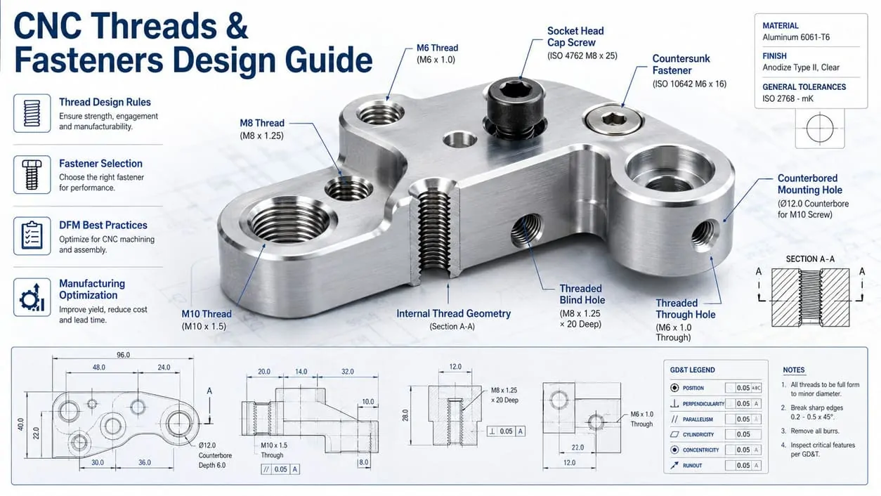
In practice, many machining issues originate from thread-related design decisions. Excessive thread depth, non-standard thread specifications, insufficient wall thickness, poor fastener selection, and improperly designed threaded holes can all increase machining complexity and lead to unnecessary production expenses. These issues are often identified during Design for Manufacturability (DFM) reviews, where manufacturers evaluate whether a design can be produced efficiently while maintaining quality requirements. Applying design for manufacturability (DFM) principles early in the design stage can help prevent costly revisions later in production.
A well-designed threaded feature should achieve more than simply holding components together. It should provide sufficient strength, support reliable assembly, simplify manufacturing processes, and minimize long-term maintenance concerns. Achieving this balance requires engineers to consider thread standards, engagement length, material properties, machining methods, and fastener selection from the earliest stages of product development.
At NAITE TECH, threaded features are among the most frequently reviewed elements during precision CNC machining services projects. Through years of manufacturing experience across industries such as industrial automation, robotics, electronics, automotive, and aerospace, we have found that relatively small adjustments to thread design can often reduce machining costs, improve assembly performance, and shorten production lead times.
This guide provides practical engineering recommendations for designing CNC threads and selecting fasteners, including thread standards, engagement rules, tapped hole design, material-specific considerations, manufacturing methods, DFM guidelines, and common design mistakes to avoid. Whether you are developing a prototype or preparing a design for high-volume production, these best practices can help improve both product performance and manufacturability.
Whether you're designing threaded holes for prototype parts or optimizing assemblies for production, this guide provides practical engineering recommendations to improve thread performance, reduce machining costs, and avoid common manufacturability issues. You'll learn how to select the right thread standards, determine proper thread engagement, choose suitable fasteners, and apply proven DFM strategies to create stronger, more manufacturing-friendly designs.
Understand the differences between Metric (M), UNC, UNF, and UNEF threads, and learn how selecting standardized thread sizes can simplify manufacturing, improve fastener availability, and reduce production costs.
Learn recommended thread engagement lengths for aluminum, steel, stainless steel, and plastics to achieve reliable mechanical strength without unnecessary machining or overdesign.
Explore best practices for blind holes, through holes, chip evacuation, thread relief, and bottom clearance to improve thread quality and reduce manufacturing risks.
Compare fastener materials, thread types, and assembly requirements to choose the most suitable fastening solution for your application and operating environment.
Discover how thread requirements vary between aluminum, stainless steel, titanium, brass, and plastic components, and learn material-specific design recommendations.
Compare common thread manufacturing methods and understand when thread milling offers advantages over traditional tapping operations in CNC machining.
Learn how manufacturers evaluate threaded features during DFM reviews to improve production efficiency, increase tool life, and avoid costly revisions.
Understand how thread depth, hole type, material selection, and non-standard specifications directly affect machining time, tooling requirements, and production cost.
Identify the most frequent thread design errors that lead to assembly failures, thread damage, tool breakage, higher costs, and unnecessary engineering changes.
Request a CNC Machining QuoteThreaded features are among the most widely used mechanical elements in CNC machined parts. Whether securing an electronic enclosure, assembling industrial equipment, or mounting critical aerospace components, threads provide a reliable method for joining parts while allowing disassembly for maintenance, repair, or future modifications.
Although threads are often considered simple design features, they have a significant impact on product performance and manufacturability. The type of thread selected, the depth of engagement, the surrounding material, and the fastening method all influence assembly strength, machining complexity, and production cost.
For this reason, threaded features are routinely reviewed during manufacturing assessments to ensure they meet both functional and production requirements.
Threads are generally classified into two categories: internal threads and external threads.
Internal threads are created inside a hole and are commonly produced through tapping, thread milling, or other thread-forming processes. These threaded holes allow screws, bolts, or threaded studs to be installed directly into a machined component. Internal threads are frequently used in housings, brackets, fixtures, mounting plates, and structural assemblies.
External threads are machined onto the outside diameter of a cylindrical feature. Examples include threaded shafts, fittings, adapters, connectors, and fastening studs. External threads are typically produced using CNC turning, single-point threading, thread milling, or thread rolling, depending on the application requirements.
Both internal and external threads must be designed with appropriate tolerances and engagement lengths to ensure proper fit, load distribution, and long-term reliability.
Modern CNC machined products rely on a wide range of fasteners to connect components and transfer loads safely throughout an assembly.
Some of the most commonly used fasteners include:
Socket head cap screws
Machine screws
Hex head bolts
Threaded studs
Set screws
Shoulder screws
Threaded inserts
Helical inserts (Helicoils)
Self-clinching fasteners
The choice of fastener depends on factors such as load requirements, material strength, assembly frequency, available installation space, and environmental conditions.
In many CNC assemblies, standard fasteners are preferred because they simplify sourcing, reduce lead times, and minimize manufacturing complexity. Designs that rely on uncommon thread sizes or specialized hardware may increase procurement costs and limit future maintenance flexibility.
Threaded features are essential across nearly every manufacturing industry.
Typical applications include:
Industry | Common Threaded Applications |
|---|---|
Industrial Equipment | Fixture plates, machine frames, mounting brackets |
Electronics | Enclosures, heat sinks, control panels |
Automotive | Sensor mounts, housings, engine accessories |
Aerospace | Lightweight brackets, instrumentation mounts |
Robotics | End effectors, actuator mounts, frame assemblies |
Medical Devices | Equipment housings and support structures |
In many of these applications, threaded holes serve not only as fastening points but also as structural features that influence load transfer, vibration resistance, and serviceability.
As products become more compact and lightweight, thread design plays an increasingly important role in balancing strength, weight reduction, and manufacturing efficiency.
A common engineering decision involves choosing between directly threaded holes and threaded inserts.
Directly tapped holes are often sufficient for steel, stainless steel, and other high-strength materials where thread wear is unlikely to be a concern.
However, softer materials such as aluminum, magnesium, and certain plastics may benefit from threaded inserts, especially when:
Frequent assembly and disassembly are expected
Higher pull-out strength is required
Long service life is critical
Thread damage could be costly to repair
Thread inserts provide hardened internal threads that improve durability and reduce the risk of stripping during repeated use.
While inserts add manufacturing and assembly cost, they can significantly increase reliability in demanding applications.
Many engineers focus primarily on thread functionality while overlooking the manufacturing implications of threaded features.
In practice, thread design decisions directly influence:
Machining cycle time
Tool life
Programming complexity
Inspection requirements
Assembly efficiency
Overall production cost
For example, excessively deep threads often increase machining time without providing meaningful improvements in strength. Similarly, blind holes with insufficient bottom clearance can increase the risk of tool breakage and thread quality issues.
Non-standard thread sizes may also require special tooling, longer setup times, and additional quality inspections.
From a supplier's perspective, well-designed threaded features are typically characterized by:
Standardized thread specifications
Appropriate thread engagement lengths
Adequate wall thickness around threaded holes
Good tool accessibility
Material-compatible fastener selection
These design choices simplify manufacturing while maintaining reliable assembly performance.
As discussed in the following sections, selecting the correct thread standard, determining proper engagement depth, and applying design-for-manufacturability principles can significantly improve both product quality and production efficiency.
These design choices simplify manufacturing while maintaining reliable assembly performance as part of a broader machining-friendly component design strategy.
Selecting the correct thread standard is one of the earliest and most important decisions in threaded feature design. The thread standard determines how mating components fit together, influences fastener availability, affects manufacturing efficiency, and impacts long-term maintenance requirements.
While thread geometry may appear similar across different standards, selecting the wrong specification can create compatibility issues, increase sourcing costs, and complicate production.
For most CNC machined parts, engineers should prioritize standardized thread systems that are widely supported by global fastener suppliers and manufacturing facilities.
Metric threads are the most commonly used thread standard worldwide and are defined by ISO metric thread specifications.
Metric threads are identified by the letter "M" followed by the nominal diameter.
Examples include:
Thread Size | Nominal Diameter |
|---|---|
M3 | 3 mm |
M4 | 4 mm |
M5 | 5 mm |
M6 | 6 mm |
M8 | 8 mm |
M10 | 10 mm |
Metric threads use millimeters for both diameter and pitch measurements, making them straightforward to specify and manufacture.
Common applications include:
Industrial automation equipment
Consumer electronics
Robotics systems
Medical devices
Aerospace components
General mechanical assemblies
Because metric threads are globally standardized, they are often the preferred choice for products intended for international markets.
Unified threads are primarily used in North America and are defined by the Unified Thread Standard (UTS).
The three most common unified thread series include:
Thread Series | Description | Typical Applications |
|---|---|---|
UNC | Unified National Coarse | General manufacturing |
UNF | Unified National Fine | Aerospace and precision assemblies |
UNEF | Unified National Extra Fine | Specialized engineering applications |
UNC threads feature a larger pitch and deeper thread profile, making them more tolerant of contamination and easier to assemble.
UNF threads provide greater clamping force and finer adjustment capability, making them suitable for vibration-sensitive or high-precision applications.
UNEF threads are generally reserved for specialized assemblies where fine adjustment or limited installation space is required.
A common engineering question is whether to use metric or imperial thread standards.
The answer largely depends on product requirements, target markets, supply chains, and existing assembly standards.
Factor | Metric Threads | Unified Threads |
|---|---|---|
Global Availability | Excellent | Moderate |
International Manufacturing | Preferred | Less Common |
North American Equipment | Less Common | Preferred |
Standardization | Excellent | Excellent |
Fastener Availability | Excellent | Excellent |
For new product development projects, metric threads are typically recommended unless compatibility with existing imperial hardware is required.
Using a single thread system throughout an assembly also helps reduce inventory complexity and minimizes assembly errors.
Another important decision involves selecting coarse or fine thread pitches.
Coarse threads generally offer:
Faster assembly
Better resistance to thread damage
Improved performance in softer materials
Lower manufacturing risk
Fine threads typically provide:
Greater adjustment precision
Higher clamping force
Improved vibration resistance
Better performance in limited installation space
For aluminum CNC machined parts, coarse threads are often preferred because they reduce the likelihood of thread stripping and simplify manufacturing.
Fine threads may be more appropriate for aerospace components, instrumentation systems, and precision mechanical assemblies.
Many engineers assume that thread size selection has little impact on manufacturing costs.
In reality, thread standardization can significantly influence production efficiency.
Standard thread sizes offer several advantages:
Standardized thread specifications also support more efficient CNC manufacturing workflows, helping engineers reduce production complexity and improve consistency across multiple components.
Readily available cutting tools
Faster CNC programming
Simplified inspection procedures
Improved fastener sourcing
Lower inventory requirements
Reduced lead times
Non-standard thread specifications may require custom tooling, special gauges, additional setup time, and more extensive quality verification.
For high-volume production, these factors can have a measurable effect on total manufacturing cost.
For most CNC machining projects, the following guidelines provide a practical starting point:
Use metric threads for globally distributed products.
Use UNC threads for general-purpose imperial assemblies.
Use UNF threads when higher clamping force or precision adjustment is required.
Standardize thread systems across the entire assembly whenever possible.
Avoid custom thread specifications unless functionally necessary.
Select thread sizes that are commonly available from global fastener suppliers.
Choosing the appropriate thread standard early in the design process helps streamline manufacturing, improve assembly consistency, and reduce long-term production costs.
In the next section, we will examine one of the most frequently misunderstood aspects of thread design: determining how much thread engagement is actually required to achieve reliable strength and performance.
One of the most common misconceptions in mechanical design is that deeper threads automatically create stronger assemblies. While thread engagement is critical for load transfer and pull-out resistance, increasing thread depth beyond a certain point often provides little additional strength while increasing machining complexity and production cost.
In CNC machining projects, excessive thread engagement is frequently identified during DFM reviews because it can lead to longer machining cycles, increased tool wear, and unnecessary manufacturing expenses. Understanding how thread engagement works allows engineers to optimize both part performance and manufacturability.
Thread engagement refers to the length of contact between the internal and external threads when a fastener is installed.
For example, when an M8 bolt is threaded into a tapped hole with 12 mm of usable thread length, the engagement length is 12 mm.
Thread engagement directly affects:
Pull-out strength
Load distribution
Thread durability
Assembly reliability
Resistance to vibration
However, thread strength is not determined by engagement length alone. Material properties, thread quality, fastener grade, and loading conditions all influence overall joint performance.
Many engineers assume that doubling thread engagement will double thread strength.
In reality, this is rarely the case.
The first few fully engaged threads typically carry the majority of the applied load. As engagement length increases, the load distribution becomes less concentrated, but the strength gains gradually diminish.
For most applications, thread engagement beyond the recommended range provides minimal improvement in pull-out resistance while increasing machining time.
For example:
Thread Size | Material | Recommended Engagement | Excessive Engagement |
|---|---|---|---|
M6 | Steel | 6 mm | 18 mm+ |
M6 | Aluminum | 9 mm | 24 mm+ |
M8 | Steel | 8 mm | 24 mm+ |
M8 | Aluminum | 12 mm | 32 mm+ |
In many cases, engagement lengths greater than 2× diameter offer little practical benefit.
A common misconception is that deeper threads always create stronger assemblies. In practice, once the engaged threads exceed the shear strength requirement of the fastener, additional thread depth often contributes little to overall joint strength while increasing machining time and tooling wear. During DFM reviews, optimizing thread engagement is one of the most effective ways to reduce manufacturing cost without affecting performance.
The ideal engagement length depends largely on the strength of the parent material.
Stronger materials require less engagement because the surrounding material is less likely to fail before the fastener.
For most carbon steel and alloy steel parts:
Recommended Engagement Length: 1.0 × Diameter
Examples:
Thread Size | Recommended Engagement |
|---|---|
M4 | 4 mm |
M6 | 6 mm |
M8 | 8 mm |
M10 | 10 mm |
Steel typically provides sufficient thread strength with relatively short engagement lengths.
For stainless steel parts:
Recommended Engagement Length: 1.0 × Diameter
Although stainless steel offers high strength, engineers should also consider thread galling risks during assembly.
Aluminum has lower shear strength than steel and generally requires longer engagement.
Recommended Engagement Length: 1.5 × Diameter
Examples:
Thread Size | Recommended Engagement |
|---|---|
M4 | 6 mm |
M6 | 9 mm |
M8 | 12 mm |
M10 | 15 mm |
This additional engagement helps compensate for the lower thread shear strength of the material.
Plastics generally require the longest engagement lengths.
Recommended Engagement Length: 2.0 × Diameter or greater
Depending on the application, threaded inserts may provide a more reliable solution than directly tapped plastic threads.
Thread engagement is closely linked to hole design.
A common mistake is specifying a thread depth equal to the total hole depth.
In reality, blind holes require additional clearance below the threaded section to accommodate:
Drill point geometry
Chip accumulation
Thread runout
Tool approach requirements
As a result, total hole depth is typically greater than usable thread engagement length.
Engineers designing threaded holes should also follow established threaded hole design best practices to ensure adequate clearance and manufacturability.
Increasing thread engagement does not always increase joint strength.
In many assemblies, the limiting factor is the fastener itself rather than the internal thread.
For example:
A low-strength screw may fail before the threads strip.
An aluminum housing may fail before the bolt reaches its maximum load.
Excessive tightening torque may damage threads regardless of engagement length.
The goal is not to maximize thread depth but to balance:
Material strength
Fastener strength
Manufacturability
Cost
Achieving this balance often results in a more efficient design than simply increasing engagement length.
Thread inserts are often recommended when:
Frequent assembly and disassembly are expected
High clamp loads are required
Soft materials are used
Long service life is critical
Thread repairability is important
Helical inserts and solid threaded inserts can significantly improve thread durability while reducing the risk of stripping.
For aluminum housings and high-cycle assemblies, inserts may provide a more reliable long-term solution than increasing thread engagement alone.
The most effective thread designs balance mechanical performance with manufacturing efficiency.
Rather than specifying maximum thread depth by default, engineers should focus on achieving sufficient engagement for the selected material and application.
Well-designed precision-machined threaded components typically use standardized engagement lengths that provide reliable strength while minimizing machining time and tooling requirements.
By applying these guidelines, manufacturers can reduce production costs, improve thread quality, and avoid unnecessary complexity without compromising assembly performance.
In the next section, we will examine how threaded hole geometry, blind hole design, chip evacuation, and machining considerations influence thread quality and manufacturability.
A well-designed threaded hole does more than simply accommodate a fastener. It directly affects thread quality, machining efficiency, assembly reliability, and production cost.
While threaded holes are among the most common features in CNC machined parts, they are also one of the most frequently revised elements during Design for Manufacturability (DFM) reviews. Issues such as insufficient bottom clearance, excessive thread depth, poor tool access, and inadequate chip evacuation can increase machining complexity and lead to avoidable manufacturing problems.
By following proven threaded hole design guidelines, engineers can improve manufacturability while maintaining the strength and functionality required for the application.
One of the first decisions when designing a threaded hole is determining whether a blind hole or through hole is required.
A blind hole has a defined depth and does not pass completely through the part.
Common applications include:
Electronic housings
Cosmetic surfaces
Sealed assemblies
Components with limited installation space
A through hole passes entirely through the component and is generally easier to manufacture.
Common applications include:
Fixture plates
Structural brackets
Industrial equipment
Mechanical assemblies
From a manufacturing perspective, through holes are often preferred because they simplify chip evacuation, improve tool accessibility, and reduce machining risk.
Design Type | Manufacturing Difficulty | Chip Evacuation | Tool Life |
|---|---|---|---|
Through Hole | Low | Excellent | Longer |
Blind Hole | Moderate | Limited | Shorter |
Whenever functional requirements allow, through holes are usually the more production-friendly option.
A common design mistake is specifying thread depth equal to hole depth.
In reality, threaded holes require additional clearance below the usable threads.
This clearance accommodates:
Drill point geometry
Chip accumulation
Tap runout
Tool approach distance
Without sufficient bottom clearance, thread quality may deteriorate near the bottom of the hole, and the risk of tool damage increases significantly.
A practical guideline is to provide additional depth beyond the required thread engagement length whenever possible.
For example:
Required Thread Engagement | Recommended Hole Depth |
|---|---|
10 mm | 13–15 mm |
15 mm | 18–20 mm |
20 mm | 24–26 mm |
The exact values depend on thread size, material, and machining method.
Chip evacuation is one of the most overlooked aspects of threaded hole design.
During tapping operations, chips generated by the cutting process must be removed efficiently from the hole.
Poor chip evacuation can lead to:
Thread damage
Poor surface finish
Increased tool wear
Tap breakage
Dimensional inaccuracies
Chip evacuation becomes increasingly important when machining:
Deep blind holes
Small thread sizes
Aluminum alloys
Stainless steel
High-volume production components
Through holes naturally allow chips to exit the opposite side of the part, making them easier to machine than blind holes.
For blind holes, engineers should avoid excessive depth whenever possible and provide sufficient space below the threaded region.
Even perfectly dimensioned threads can become difficult or expensive to manufacture if tooling access is restricted.
When designing threaded features, consider:
Available spindle clearance
Tool holder dimensions
Fixture accessibility
Adjacent walls and features
Fastener installation access
Threads positioned too close to vertical walls, deep pockets, or complex internal geometries may require specialized tooling or additional machining operations.
Good accessibility simplifies manufacturing and often improves thread consistency.
Engineers should also follow established threaded hole design best practices when positioning threaded features within a component.
Thread relief is a small clearance feature located at the end of a threaded section.
Although often overlooked, thread relief serves several important purposes:
Allows full thread formation
Reduces stress concentrations
Improves fastener seating
Simplifies manufacturing
Without proper relief, incomplete threads may develop near the bottom of blind holes or at the end of externally threaded features.
In precision assemblies, these incomplete threads can interfere with proper fastener engagement and assembly performance.
Adding thread relief is a simple design modification that can significantly improve thread quality.
Internal threads are commonly produced using either tapping or thread milling.
Each method offers distinct advantages depending on thread size, material, and production requirements.
Factor | Tapping | Thread Milling |
|---|---|---|
Production Speed | Faster | Slower |
Tool Cost | Lower | Higher |
Flexibility | Limited | Excellent |
Large Threads | Less Suitable | Excellent |
Blind Holes | Moderate | Good |
Tool Breakage Risk | Higher | Lower |
Thread Accuracy | Good | Excellent |
For deep blind holes and high-value components, thread milling often provides greater process reliability than tapping. Although cycle times may be slightly longer, reduced breakage risk and improved thread consistency frequently offset the additional machining cost.
Tapping is often the preferred solution for standard thread sizes in high-volume production because it is fast and cost-effective.
Thread milling is frequently chosen when:
Large thread diameters are required
Difficult materials are being machined
Thread accuracy is critical
Blind holes are involved
Tool breakage risk must be minimized
Manufacturers offering advanced multi-surface CNC milling capabilities can often produce complex threaded features using thread milling strategies that improve accuracy and reduce tooling risks.
Many manufacturing issues can be prevented during the design stage.
Common threaded hole design mistakes include:
Specifying unnecessary thread depth
Omitting bottom clearance
Using blind holes where through holes are acceptable
Ignoring chip evacuation requirements
Restricting tool access
Selecting thread sizes that are difficult to machine
Positioning threaded holes too close to edges
These issues often increase machining time without improving product performance.
By applying practical design-for-manufacturability principles early in development, engineers can reduce risk while improving production efficiency.
Threaded holes should be designed not only for assembly performance but also for efficient manufacturing.
Production-friendly threaded features typically include:
Appropriate engagement lengths
Adequate bottom clearance
Good chip evacuation paths
Accessible machining locations
Standardized thread specifications
Reliable fastening strategies
When combined with proper thread selection and material-specific design practices, these guidelines help create stronger, more manufacturable components while reducing overall production costs.
The next section focuses on selecting the right fasteners, including material selection, coarse versus fine threads, corrosion considerations, and when thread inserts should be used to improve long-term assembly reliability.
Choosing the correct fastener is just as important as designing the threaded feature itself. Even a perfectly machined thread can fail prematurely if the wrong fastener material, thread type, or fastening strategy is selected.
Fasteners influence assembly strength, vibration resistance, corrosion performance, service life, and maintenance requirements. In many cases, optimizing fastener selection can improve joint reliability more effectively than increasing thread engagement or tightening torque.
When designing CNC machined parts, engineers should evaluate fastener requirements early in the development process to ensure compatibility with the selected material, operating environment, and manufacturing objectives.
Fastener material plays a critical role in determining mechanical performance and environmental resistance.
Common fastener materials include:
Material | Advantages | Typical Applications |
|---|---|---|
Carbon Steel | High strength, low cost | General industrial assemblies |
Stainless Steel | Corrosion resistance | Outdoor and marine environments |
Alloy Steel | High strength | Structural applications |
Titanium | High strength-to-weight ratio | Aerospace and lightweight systems |
Brass | Corrosion resistance and conductivity | Electrical and electronic equipment |
Material selection should always consider both mechanical loads and environmental exposure.
For example, a carbon steel fastener may provide sufficient strength but perform poorly in corrosive environments, while stainless steel fasteners may offer superior corrosion resistance but lower strength in certain grades.
Thread pitch selection is another important design decision.
Coarse threads have a larger pitch and deeper thread profile, making them easier to manufacture and more resistant to damage during assembly.
Advantages of coarse threads include:
Faster installation
Improved resistance to stripping
Better performance in softer materials
Greater tolerance to contamination
Lower manufacturing risk
Fine threads offer a greater number of threads per unit length and are commonly used in precision assemblies.
Advantages of fine threads include:
Higher clamping force
Improved vibration resistance
More precise adjustment
Better performance in limited installation space
For most aluminum CNC machined components, coarse threads are generally preferred because they provide more reliable engagement and lower risk of thread damage.
During DFM reviews, coarse threads are typically recommended for aluminum housings, fixture components, and general industrial assemblies. Fine threads can provide higher clamping performance, but they are often more susceptible to damage in softer materials and may increase manufacturing complexity.
Fastener selection should also consider corrosion resistance and material compatibility.
A common mistake is pairing dissimilar metals without evaluating galvanic corrosion risks.
Examples include:
Stainless steel fasteners in aluminum components
Titanium fasteners in aluminum structures
Carbon steel fasteners exposed to moisture
When two dissimilar metals are in electrical contact and exposed to an electrolyte such as water or humidity, galvanic corrosion can occur.
Potential solutions include:
Applying protective coatings
Using insulating washers
Selecting compatible materials
Adding corrosion-resistant surface treatments
Engineers should consider the operating environment during the initial design phase rather than addressing corrosion issues after production begins.
Aluminum is one of the most commonly machined materials, but its relatively low shear strength requires special attention when selecting fasteners.
Key recommendations include:
Use coarse thread profiles whenever possible.
Increase thread engagement length to approximately 1.5× diameter.
Avoid excessive tightening torque.
Consider thread inserts for high-cycle assemblies.
Evaluate pull-out requirements carefully.
Repeated assembly and disassembly can gradually wear aluminum threads, reducing long-term reliability.
For products requiring frequent maintenance, thread inserts often provide a more durable solution.
Thread inserts are designed to strengthen threaded connections and improve wear resistance.
Common insert types include:
Helical wire inserts (Helicoils)
Solid threaded inserts
Keenserts
Press-fit inserts
Heat-set inserts for plastics
Thread inserts are particularly valuable when:
Soft materials are used
Frequent assembly is expected
High clamp loads are required
Thread repairability is important
Long service life is critical
Although inserts add manufacturing and assembly costs, they can significantly improve long-term reliability in demanding applications.
Engineers often face the decision between directly tapped threads and threaded inserts.
Factor | Tapped Threads | Thread Inserts |
|---|---|---|
Initial Cost | Lower | Higher |
Assembly Durability | Moderate | Excellent |
Thread Wear Resistance | Moderate | Excellent |
Repairability | Limited | Good |
Pull-Out Strength | Good | Excellent |
Repeated Assembly | Moderate | Excellent |
One common misconception is that increasing thread depth always eliminates stripping concerns in aluminum parts. In many cases, a properly selected thread insert provides a greater improvement in durability and pull-out resistance than simply extending thread engagement length.
For prototype parts and low-cycle applications, directly tapped threads are often sufficient.
For production components subject to repeated assembly or high loads, inserts may provide a better long-term solution.
Fastener selection should also account for assembly accessibility.
Questions engineers should consider include:
Can installation tools reach the fastener easily?
Is there sufficient clearance for tightening?
Will maintenance access be required in the future?
Can the fastener be installed without damaging surrounding features?
Poor accessibility often increases assembly time and maintenance costs.
In some cases, modifying the fastener type or thread location can simplify assembly without affecting performance.
Standardizing fastener specifications across a product family offers several benefits:
Reduced inventory requirements
Simplified procurement
Lower assembly complexity
Improved maintenance support
Faster production setup
Whenever possible, engineers should minimize the number of unique fastener types used within an assembly.
This approach not only reduces manufacturing costs but also improves long-term serviceability.
Manufacturers providing advanced CNC manufacturing solutions often recommend fastener standardization during DFM reviews because it improves efficiency throughout the entire product lifecycle.
Successful threaded assemblies depend on more than thread geometry alone.
The most reliable designs combine:
Appropriate fastener materials
Compatible thread standards
Proper engagement lengths
Corrosion-resistant design practices
Good assembly accessibility
Application-specific fastening strategies
By selecting fasteners based on functional requirements rather than convenience alone, engineers can improve product reliability, reduce maintenance concerns, and create more robust assemblies.
In the next section, we will explore how thread design requirements change across different materials, including aluminum, stainless steel, titanium, brass, and engineering plastics.
Not all materials respond to threaded features in the same way. Material strength, hardness, ductility, and wear resistance all influence how threads perform during machining and throughout the product’s service life.
A thread design that performs well in steel may fail prematurely in aluminum, while a thread specification suitable for stainless steel may create unnecessary manufacturing challenges when applied to plastics or titanium.
For this reason, engineers should adapt thread design strategies based on the properties of the parent material rather than applying a one-size-fits-all approach.
Aluminum is one of the most commonly used materials in CNC machining due to its excellent machinability, lightweight characteristics, and corrosion resistance.
However, aluminum threads are more susceptible to stripping than steel threads because of the material's lower shear strength.
When designing threaded features in aluminum components, consider the following guidelines:
Use approximately 1.5× diameter thread engagement.
Prefer coarse thread pitches when possible.
Avoid excessive tightening torque.
Maintain sufficient wall thickness around threaded holes.
Consider thread inserts for high-cycle assemblies.
Common examples include:
Thread Size | Recommended Engagement |
|---|---|
M4 | 6 mm |
M6 | 9 mm |
M8 | 12 mm |
M10 | 15 mm |
For assemblies requiring frequent maintenance, thread inserts often provide greater durability than increasing thread depth.
In aluminum housings and fixture components, thread stripping is typically caused by insufficient material strength rather than inadequate thread depth. In many applications, adding a thread insert or increasing local wall thickness delivers greater performance improvements than extending thread engagement beyond recommended values.
Stainless steel provides excellent corrosion resistance and good mechanical strength, making it a popular choice for industrial, medical, and marine applications.
Compared with aluminum, stainless steel threads generally require less engagement length.
Recommended guidelines include:
Use approximately 1.0× diameter engagement.
Avoid unnecessary thread depth.
Use proper lubrication during assembly.
Consider galling prevention strategies.
Ensure compatible fastener materials are selected.
One of the most significant challenges with stainless steel assemblies is thread galling.
Thread galling occurs when friction causes material transfer between mating threads, potentially leading to seizure during assembly or disassembly.
To reduce galling risk:
Use anti-seize compounds.
Avoid excessive tightening speeds.
Consider coated fasteners.
Use dissimilar material combinations where appropriate.
Steel offers some of the strongest and most durable internal threads available in CNC machined components.
Because of its high strength, steel generally requires less thread engagement than softer materials.
Typical recommendations include:
Use approximately 1.0× diameter engagement.
Standard tapped holes are usually sufficient.
Thread inserts are rarely required unless repairability is important.
Standard thread pitches are generally preferred.
Steel components often provide excellent pull-out resistance without requiring deep threaded features.
As a result, overdesigning thread depth in steel parts frequently increases machining costs without producing meaningful strength gains.
Titanium is widely used in aerospace, medical, motorsport, and high-performance engineering applications because of its exceptional strength-to-weight ratio and corrosion resistance.
However, titanium presents unique machining challenges.
Engineers designing threaded features in titanium should consider:
Tool wear rates are significantly higher than in aluminum.
Thread machining cycles are typically longer.
Heat generation can affect thread quality.
Galling risks may increase during assembly.
Recommended practices include:
Standardized thread specifications.
Appropriate cutting parameters.
Controlled assembly torque.
Surface treatment considerations.
Adequate thread relief features.
Because titanium machining is relatively expensive, production-friendly thread design becomes particularly important.
Brass is frequently used for electrical systems, instrumentation components, fluid handling equipment, and decorative applications.
Advantages of brass threads include:
Good machinability
Excellent corrosion resistance
Low friction characteristics
Good dimensional stability
Typical recommendations include:
Standard thread engagement lengths.
Conventional thread forms.
Avoid excessive tightening torque.
Consider assembly load requirements carefully.
Although brass is relatively easy to machine, thread strength is generally lower than steel and should be evaluated accordingly.
Plastics require special consideration because their mechanical behavior differs significantly from metals.
Challenges associated with plastic threads include:
Lower thread strength
Creep deformation
Wear during repeated assembly
Thermal expansion effects
Recommended guidelines include:
Use engagement lengths of approximately 2× diameter or greater.
Minimize tightening torque.
Avoid fine thread pitches.
Consider heat-set or threaded inserts.
Design for repeated assembly when necessary.
For high-cycle products, inserts often provide a more reliable solution than directly threaded plastic holes.
In engineering plastics and polymer-based components, thread failure often occurs gradually through wear and deformation rather than sudden stripping. For assemblies requiring frequent maintenance, threaded inserts can significantly improve long-term reliability and service life.
The table below summarizes common thread engagement recommendations for CNC machined parts.
Material | Recommended Engagement |
|---|---|
Steel | 1.0 × Diameter |
Stainless Steel | 1.0 × Diameter |
Aluminum | 1.5 × Diameter |
Brass | 1.0–1.5 × Diameter |
Titanium | 1.0 × Diameter |
Plastics | 2.0 × Diameter or More |
These values provide a practical starting point for most engineering applications.
Actual requirements may vary depending on:
Fastener grade
Load conditions
Safety factors
Environmental exposure
Assembly frequency
Material choice influences far more than mechanical performance.
It also affects:
Thread quality
Tool life
Machining time
Production cost
Assembly reliability
For example, aluminum generally offers excellent machinability but may require longer engagement lengths. Titanium provides exceptional strength but increases machining complexity and tooling costs. Plastics simplify weight reduction but often require additional reinforcement strategies.
When evaluating threaded features, engineers should consider both product performance and manufacturing efficiency.
Manufacturers offering complex precision machining capabilities frequently review material-specific thread requirements during DFM assessments to ensure the final design balances strength, cost, and manufacturability.
Successful thread design begins with understanding the behavior of the parent material.
Rather than applying the same thread specifications across every component, engineers should tailor engagement lengths, thread forms, and fastening strategies to match material properties.
By considering material-specific requirements early in the design process, manufacturers can improve assembly reliability, reduce machining risk, and optimize production efficiency.
The next section examines the manufacturing methods used to create threads, including tapping, thread milling, single-point threading, and other processes commonly used in CNC machining.
Thread quality depends not only on design but also on the manufacturing method used to create the threads. Different machining processes offer varying levels of accuracy, flexibility, production speed, and cost efficiency.
Selecting the most appropriate thread manufacturing method can improve dimensional consistency, reduce machining risks, and optimize overall production costs.
During production planning, manufacturers typically evaluate factors such as thread size, material type, production volume, tolerance requirements, and part geometry before determining the most suitable threading process.
Tapping is the most widely used process for producing internal threads in CNC machined components.
The process uses a cutting or forming tap to create threads inside a pre-drilled hole.
Advantages of tapping include:
Fast cycle times
Low tooling costs
Excellent efficiency for standard thread sizes
Suitable for high-volume production
Simple programming requirements
Typical applications include:
M3 to M12 threaded holes
Electronic enclosures
Industrial equipment
Automotive components
General mechanical assemblies
Because of its speed and cost efficiency, tapping is often the preferred method for standard internal threads.
However, tapping also presents several limitations:
Higher risk of tool breakage
Reduced flexibility for custom thread sizes
More challenging chip evacuation in blind holes
Greater sensitivity to difficult materials
For these reasons, tapping may not always be the optimal solution for complex or high-value parts.
Thread milling uses a rotating cutter that follows a helical toolpath to generate thread geometry.
Unlike tapping, the thread profile is created through controlled CNC interpolation.
Advantages of thread milling include:
Excellent dimensional control
Reduced risk of catastrophic tool failure
Ability to machine multiple thread sizes
Better performance in difficult materials
Improved chip evacuation
Suitable for large-diameter threads
Thread milling is particularly valuable when producing:
Large threaded holes
Blind-hole threads
High-value aerospace components
Titanium parts
Stainless steel components
Prototype and low-volume production parts
Manufacturers with advanced CNC milling technologies often prefer thread milling for critical threaded features because it provides greater process reliability and flexibility.
For high-value components, thread milling often reduces overall manufacturing risk despite longer cycle times. If a thread mill fails, the workpiece can frequently be recovered. In contrast, a broken tap inside a finished component may render the part unusable, especially in small blind holes.
One of the most common questions engineers ask is whether tapping or thread milling should be used.
The answer depends on the application.
Factor | Tapping | Thread Milling |
|---|---|---|
Cycle Time | Faster | Slower |
Tool Cost | Lower | Higher |
Programming Complexity | Lower | Higher |
Thread Accuracy | Good | Excellent |
Large Thread Sizes | Limited | Excellent |
Blind Holes | Moderate | Excellent |
Tool Breakage Risk | Higher | Lower |
Flexibility | Limited | Excellent |
In general:
Tapping is preferred for standard production threads.
Thread milling is preferred for complex, large, or critical threaded features.
The most cost-effective option is not always the fastest process. Manufacturers often evaluate overall process reliability rather than machining speed alone.
External threads are commonly produced using single-point threading operations on CNC lathes.
In this process, a threading tool progressively cuts the thread profile through multiple passes.
Advantages include:
High dimensional accuracy
Excellent profile control
Suitable for custom thread forms
Effective for large-diameter threads
Compatible with a wide range of materials
Typical applications include:
Threaded shafts
Hydraulic fittings
Connectors
Precision adapters
Aerospace hardware
Single-point threading remains one of the most versatile methods for producing external threads.
Thread rolling differs from cutting processes because material is displaced rather than removed.
The process forms threads through plastic deformation.
Benefits include:
Improved thread strength
Better surface finish
Increased fatigue resistance
Faster production rates
No chip generation
However, thread rolling is generally limited to specific materials and production scenarios.
It is most commonly used for:
Fasteners
Studs
High-volume production components
Because specialized tooling is required, thread rolling is less common in custom CNC machining environments.
Some materials require additional consideration during thread machining.
Examples include:
Material | Common Challenges |
|---|---|
Titanium | Heat generation, tool wear |
Stainless Steel | Work hardening, galling |
Inconel | High cutting forces |
Hardened Steel | Tool wear |
Engineering Plastics | Deformation and burr formation |
When machining these materials, manufacturers may adjust:
Cutting speeds
Feed rates
Tool geometries
Coolant strategies
Threading methods
Selecting the appropriate manufacturing process becomes increasingly important as material complexity increases.
For titanium and stainless steel components, process stability often becomes more important than cycle time. Manufacturers frequently choose thread milling over tapping because improved chip control and reduced tool breakage risks help maintain consistent quality across production runs.
Thread manufacturing decisions are also affected by part geometry.
Engineers often focus on thread specifications while overlooking accessibility and machining constraints.
Factors that may influence process selection include:
Deep cavities
Narrow pockets
Angled surfaces
Limited tool clearance
Thin-wall structures
Multi-axis features
Complex geometries may require specialized machining strategies to maintain thread quality.
Components with angled or difficult-to-access threaded features often benefit from simultaneous 5-axis machining expertise, which enables improved tool orientation and greater machining flexibility.
Different threading methods can have a significant impact on production cost.
Factors affecting cost include:
Tooling requirements
Machining time
Setup complexity
Inspection requirements
Scrap risk
Material machinability
For example:
Standard tapped holes generally offer the lowest cost.
Thread milling may increase cycle time but reduce scrap risk.
Custom thread profiles often require additional setup and inspection.
The most economical solution depends on the balance between production volume, quality requirements, and manufacturing risk.
Thread-related issues are among the most common findings during DFM evaluations.
Manufacturers routinely assess:
Thread size selection
Hole accessibility
Engagement depth
Material compatibility
Tool clearance
Thread standardization
Early identification of potential manufacturing challenges can prevent costly revisions later in production.
Teams providing end-to-end CNC machining support often recommend thread modifications that simplify machining while maintaining functional performance.
No single threading process is ideal for every application.
Successful thread manufacturing depends on selecting the process that best matches:
Material characteristics
Production volume
Thread size
Accuracy requirements
Part geometry
Cost objectives
By understanding the strengths and limitations of tapping, thread milling, single-point threading, and thread rolling, engineers can make informed design decisions that improve both manufacturability and long-term product performance.
The next section focuses on Design for Manufacturability (DFM) guidelines for threaded features, including wall thickness considerations, edge distances, accessibility requirements, and common design practices that reduce production cost.
Designing functional threads is only part of the engineering challenge. Equally important is ensuring that threaded features can be manufactured efficiently, consistently, and cost-effectively.
Design for Manufacturability (DFM) focuses on optimizing part geometry to reduce machining complexity, minimize production risks, and improve overall manufacturing efficiency. Threaded features are among the most frequently reviewed elements during DFM assessments because relatively small design changes can have a significant impact on machining time, tooling requirements, and product cost.
By applying proven DFM principles early in development, engineers can improve both product performance and production efficiency.
One of the simplest ways to improve manufacturability is to standardize thread specifications throughout an assembly.
Using a limited number of thread sizes provides several advantages:
Reduced tooling requirements
Faster machine setup
Simplified inspection procedures
Improved fastener sourcing
Lower inventory complexity
Easier maintenance and repair
For example, a product using only M4, M6, and M8 threads is typically easier to manufacture and support than a design containing numerous unique thread sizes.
Whenever possible, engineers should avoid custom thread specifications unless there is a clear functional requirement.
During DFM reviews, thread standardization is often one of the fastest ways to reduce manufacturing complexity. Consolidating multiple thread sizes into a smaller set of standard specifications can simplify production planning, reduce tooling changes, and improve assembly efficiency without affecting product performance.
Threaded holes positioned too close to exterior surfaces can weaken the surrounding material and increase the risk of cracking, deformation, or thread failure.
Adequate material thickness around threaded features is essential for:
Thread strength
Structural integrity
Machining stability
Long-term durability
This consideration becomes particularly important in aluminum components and thin-wall designs.
Engineers should follow established wall thickness design recommendations for CNC machining when positioning threaded features near edges, pockets, and external surfaces.
As a general guideline:
Larger thread sizes require greater surrounding material.
Thin walls may reduce thread strength.
High-load applications often require additional reinforcement.
Proper wall thickness not only improves mechanical performance but also reduces machining vibration and improves dimensional consistency.
Threaded holes located near part edges create several manufacturing challenges.
Potential risks include:
Material breakout
Reduced thread quality
Tool deflection
Structural weakening
Increased inspection requirements
Although exact distances depend on material and thread size, engineers should provide sufficient edge clearance whenever possible.
If space constraints exist, alternative fastening methods such as threaded inserts or redesigned mounting features may provide a better solution.
Even correctly sized threads can become difficult and expensive to manufacture when tool access is restricted.
Common accessibility issues include:
Deep pockets
Narrow cavities
Tall surrounding walls
Complex internal geometries
Limited spindle clearance
Poor accessibility often increases machining time and may require specialized tooling.
Components designed using machining-friendly part geometry principles generally allow more efficient thread production and improve overall manufacturing reliability.
One of the most common examples of overengineering is excessive thread depth.
As discussed earlier, increasing engagement beyond recommended values rarely provides proportional improvements in strength.
However, deeper threads often result in:
Longer cycle times
Increased tool wear
Higher machining costs
Greater tapping risks
Reduced process efficiency
For most applications:
Steel: approximately 1× diameter
Aluminum: approximately 1.5× diameter
Plastics: approximately 2× diameter
These values provide sufficient engagement for the majority of threaded assemblies.
Designing deeper threads simply because additional space is available usually offers little practical benefit.
Threaded features are often positioned inside pockets, recessed mounting areas, and other internal geometries.
When internal corners are too sharp, machining becomes more difficult because cutting tools cannot create perfectly square internal corners.
As a result, designers should consider internal corner radius optimization strategies when creating threaded mounting features within pockets and enclosed cavities.
Benefits include:
Improved tool access
Faster machining
Better surface finish
Reduced tool wear
Lower manufacturing cost
This consideration becomes especially important for components containing multiple threaded holes within machined recesses.
Thread quality depends heavily on the quality of the hole created before threading begins.
Problems such as:
Incorrect pilot hole diameter
Insufficient bottom clearance
Poor chip evacuation
Improper hole depth
can negatively affect final thread performance.
Engineers should apply CNC hole feature design guidelines to ensure threaded holes can be manufactured efficiently and consistently.
Important considerations include:
Blind vs through-hole selection
Hole depth requirements
Drill point clearance
Chip evacuation paths
Tool accessibility
Many thread-related manufacturing issues originate during hole creation rather than during the threading operation itself.
DFM is not limited to machining considerations.
Assembly efficiency also plays an important role.
Reducing the number of unique fasteners within a product can provide significant benefits:
Faster assembly
Reduced inventory
Lower procurement costs
Simplified maintenance
Reduced assembly errors
Whenever possible, engineers should standardize both thread sizes and fastener types across the product.
This approach often improves manufacturing efficiency throughout the entire product lifecycle.
Some threaded features cannot be accessed using conventional 3-axis machining setups.
Examples include:
Angled threaded holes
Compound geometries
Deep recessed features
Multi-face components
In these situations, advanced machining strategies may be required.
Manufacturers offering complex multi-axis machining solutions can often produce these features more efficiently by reducing setups and improving tool orientation.
Evaluating these requirements early helps prevent costly redesigns during production.
The best threaded designs are not necessarily the strongest or most complex.
They are the designs that achieve functional requirements while remaining practical to manufacture.
Production-friendly threaded features typically include:
Standardized thread sizes
Appropriate engagement lengths
Adequate wall thickness
Good tool accessibility
Proper hole geometry
Efficient assembly strategies
By incorporating these DFM principles early in the design process, engineers can improve thread quality, reduce production costs, and accelerate manufacturing timelines.
The next section examines the most common thread design mistakes engineers make and provides practical recommendations for avoiding costly manufacturing and assembly problems.
Even experienced engineers occasionally encounter thread-related issues during product development. In many cases, the problem is not the thread itself but how the threaded feature interacts with material properties, assembly requirements, and manufacturing constraints.
During Design for Manufacturability (DFM) reviews, threaded features are among the most frequently revised elements because small design decisions can significantly affect machining efficiency, assembly performance, and long-term reliability.
Understanding the most common thread design mistakes helps engineers avoid unnecessary costs, reduce production risks, and improve product performance from the earliest design stages.
One of the most common misconceptions is that deeper threads always create stronger assemblies.
As discussed earlier, thread strength does not increase proportionally with engagement length.
Excessive thread depth often results in:
Longer machining cycles
Increased tool wear
Higher production costs
Greater tapping risks
More difficult chip evacuation
For most applications:
Material | Recommended Engagement |
|---|---|
Steel | 1.0 × Diameter |
Stainless Steel | 1.0 × Diameter |
Aluminum | 1.5 × Diameter |
Plastics | 2.0 × Diameter |
Designing thread depths far beyond these values rarely produces meaningful performance improvements.
Blind holes are often selected by default without considering manufacturing implications.
Compared with through holes, blind holes generally:
Increase chip evacuation challenges
Raise tool breakage risk
Require additional bottom clearance
Increase machining complexity
Extend cycle times
Whenever functional requirements permit, through holes typically provide a more manufacturing-friendly solution.
Engineers should evaluate whether a blind hole is truly necessary before finalizing the design.
Thread quality depends heavily on the hole created before threading begins.
Common hole-related problems include:
Incorrect pilot hole diameter
Insufficient bottom clearance
Poor chip evacuation
Excessive hole depth
Inadequate tool access
Many of these issues can be avoided by following established threaded feature preparation guidelines during the hole design stage.
When hole geometry is optimized, thread quality and manufacturing consistency typically improve as well.
Custom thread specifications are sometimes necessary, but they should not become the default choice.
Non-standard thread sizes often lead to:
Specialized tooling requirements
Longer setup times
Increased inspection complexity
Higher procurement costs
Reduced fastener availability
Whenever possible, engineers should use commonly available metric or unified thread standards.
Standardization improves both manufacturability and long-term serviceability.
Threaded holes placed near edges can weaken surrounding material and create manufacturing challenges.
Potential consequences include:
Cracking
Material breakout
Reduced thread strength
Distortion during machining
Lower assembly reliability
The risk becomes even greater in softer materials such as aluminum and plastics.
Providing adequate edge distance improves both structural performance and thread quality.
Threaded holes require enough surrounding material to support loading forces.
Designs with thin walls often experience:
Reduced pull-out strength
Local deformation
Thread stripping
Vibration-related failures
Engineers should apply material-support design practices for threaded features when placing threaded holes in lightweight or space-constrained components.
This consideration is particularly important for aluminum housings and thin-wall machined parts.
Thread failures in aluminum components are frequently attributed to insufficient surrounding material rather than poor thread quality. Increasing local wall thickness often improves performance more effectively than increasing thread depth.
A thread may appear perfectly functional in CAD but remain difficult to manufacture.
Accessibility problems commonly occur when threaded features are positioned inside:
Deep pockets
Narrow cavities
Recessed mounting locations
Complex internal geometries
Poor accessibility often results in:
Longer cycle times
Additional setups
Specialized tooling
Increased manufacturing costs
Designs developed using efficient CNC design strategies generally achieve better manufacturability and more consistent thread quality.
Even well-designed threads can fail if paired with inappropriate fasteners.
Common examples include:
Fine threads in soft aluminum
Corrosion-prone material combinations
Overly high-strength fasteners in weak materials
Fasteners requiring excessive torque
Fastener selection should always consider:
Material strength
Environmental exposure
Service requirements
Maintenance frequency
Thread performance depends on the entire fastening system, not just the threaded hole.
Some engineers attempt to compensate for wear concerns by increasing thread depth.
However, repeated assembly and disassembly can eventually damage threads regardless of engagement length.
Thread inserts should be considered when:
Frequent maintenance is expected
Long service life is required
Soft materials are used
High clamp loads are present
In many situations, inserts provide a more reliable long-term solution than deeper threads.
Perhaps the most costly mistake is designing threaded features without considering manufacturing requirements.
Engineers often optimize for:
Mechanical performance
Space constraints
Assembly requirements
while overlooking:
Tool accessibility
Machining strategy
Production cost
Inspection requirements
Process reliability
Collaborating with manufacturing teams early in development helps identify potential issues before production begins.
Manufacturers offering engineering-supported CNC production services frequently provide DFM recommendations that improve both manufacturability and product performance.
Most thread-related manufacturing problems share one characteristic: they are significantly easier and less expensive to correct during design than during production.
A successful thread design should balance:
Mechanical strength
Assembly reliability
Material behavior
Manufacturing efficiency
Cost objectives
By understanding and avoiding these common mistakes, engineers can create threaded features that perform reliably while remaining practical and cost-effective to manufacture.
In the next section, we will examine how thread design decisions directly influence machining cost, production efficiency, tooling requirements, and overall project economics.
Threaded features may appear to be small details within a larger component, but they often have a measurable impact on manufacturing cost, machining time, tooling requirements, and overall production efficiency.
In many CNC machining projects, thread-related decisions influence far more than assembly performance. Factors such as thread depth, hole geometry, thread standardization, material selection, and manufacturing method can directly affect cycle times and production economics.
Understanding these cost drivers allows engineers to make informed design decisions that balance performance requirements with manufacturing efficiency.
Unlike simple drilled holes, threaded features require additional machining operations.
Depending on the application, thread production may involve:
Drilling
Reaming
Tapping
Thread milling
Deburring
Inspection
Each operation adds time to the manufacturing process.
For example, producing a standard drilled hole may require only a few seconds, while creating a precision threaded feature often requires multiple operations and additional quality verification.
As thread quantity increases, total machining time can rise significantly.
One of the most overlooked cost drivers is excessive thread depth.
Many engineers assume that adding extra thread engagement has little effect on production.
In reality, deeper threads often require:
Longer tapping cycles
Increased thread milling time
Additional chip evacuation
Greater tool wear
Higher risk of tool failure
For example:
Thread Size | Recommended Engagement | Overdesigned Engagement |
|---|---|---|
M6 in Aluminum | 9 mm | 24 mm |
M8 in Aluminum | 12 mm | 32 mm |
M10 in Steel | 10 mm | 30 mm |
The additional machining time associated with excessive thread depth can become substantial in medium- and high-volume production.
One of the most common opportunities for cost reduction involves optimizing thread engagement lengths. In production environments containing hundreds or thousands of threaded holes, eliminating unnecessary thread depth can significantly reduce machining time while maintaining the same functional performance.
Standardized thread specifications simplify nearly every aspect of production.
Benefits include:
Reduced tooling inventory
Faster setup times
Simplified programming
Easier inspection
Improved fastener sourcing
Lower procurement costs
By contrast, assemblies containing numerous custom thread sizes often require:
Additional tooling
Specialized gauges
Extra setup operations
Increased inventory management
Using a smaller range of standard thread sizes typically improves manufacturing efficiency across the entire product lifecycle.
Hole design also affects manufacturing cost.
Through holes generally offer:
Better chip evacuation
Faster machining
Lower tapping risk
Improved process reliability
Blind holes often require:
Additional clearance considerations
More careful chip management
Slower machining parameters
Increased inspection attention
Whenever functional requirements allow, through holes can reduce both machining complexity and production risk.
Material properties play a major role in thread manufacturing economics.
Different materials require different machining strategies.
Material | Relative Threading Cost |
|---|---|
Aluminum | Low |
Brass | Low |
Carbon Steel | Moderate |
Stainless Steel | Moderate to High |
Titanium | High |
High-Temperature Alloys | Very High |
More difficult materials often increase:
Tool wear
Machining time
Inspection requirements
Scrap risk
When evaluating design alternatives, engineers should consider not only mechanical performance but also manufacturing implications.
The selected threading method can also affect overall project economics.
Tapping generally provides:
Lower cycle times
Lower tooling costs
Excellent performance for standard threads
Thread milling generally provides:
Greater flexibility
Improved accuracy
Lower breakage risk
Better performance in difficult materials
The lowest-cost solution depends on production volume and application requirements.
For standard production parts, tapping is often the most economical choice.
For critical components, manufacturers using advanced thread machining processes may choose thread milling to improve reliability and reduce scrap risk.
Thread location matters.
Features that increase manufacturing complexity include:
Angled threaded holes
Deep recessed threads
Narrow cavities
Multi-face threaded features
Limited tool access
These conditions often require:
Additional setups
Specialized fixturing
Multi-axis machining
Extended programming time
Parts requiring advanced 5-axis machining capabilities can often reduce setup complexity and improve accessibility, but the manufacturing strategy should still be considered during the design phase.
The cost impact of threaded features extends beyond machining.
Fastener decisions also influence:
Procurement expenses
Inventory management
Assembly labor
Maintenance requirements
Using standardized fasteners throughout an assembly often reduces long-term ownership costs.
Benefits include:
Improved availability
Simplified sourcing
Reduced inventory
Faster assembly
Easier field service
In many projects, standardization provides larger cost savings than individual machining optimizations.
Threaded features are routinely evaluated during DFM reviews because they offer numerous opportunities for manufacturing optimization.
Common recommendations include:
Reducing excessive thread depth
Standardizing thread sizes
Improving accessibility
Increasing edge distances
Simplifying hole geometry
Optimizing material selection
Many of these changes can reduce manufacturing costs without affecting product functionality.
Manufacturers providing production-focused CNC engineering support often identify these opportunities before production begins, helping customers avoid unnecessary costs and delays.
Threaded features may occupy only a small portion of a component, but they frequently influence a disproportionate share of manufacturing effort.
Design choices involving:
Thread depth
Thread quantity
Hole type
Material selection
Manufacturing method
Fastener standardization
can collectively affect machining time, tooling costs, assembly efficiency, and long-term product support.
By considering these factors early in the design process, engineers can create threaded features that are not only reliable and functional but also optimized for efficient production.
In the final section, we will summarize the key thread design principles discussed throughout this guide and provide practical recommendations for achieving reliable, cost-effective CNC threaded features.
For quick reference, the table below summarizes the most important thread design recommendations discussed throughout this guide.
Design Factor | Recommended Practice | Reason |
|---|---|---|
Thread Engagement (Steel) | 1.0 × Diameter | Additional depth provides minimal strength improvement. |
Thread Engagement (Aluminum) | 1.5 × Diameter | Compensates for lower material shear strength. |
Thread Engagement (Plastic) | 2.0 × Diameter or More | Improves pull-out resistance and durability. |
Thread Type | Use Standard Metric Threads Whenever Possible | Simplifies manufacturing and sourcing. |
Hole Design | Prefer Through Holes Over Blind Holes | Improves chip evacuation and machining reliability. |
Fastener Selection | Match Fastener Material to Base Material | Reduces corrosion and compatibility issues. |
Thread Inserts | Use for High-Cycle Assemblies and Soft Materials | Improves durability and wear resistance. |
Wall Thickness | Provide Adequate Material Around Threads | Improves strength and prevents stripping. |
Accessibility | Allow Sufficient Tool Clearance | Reduces machining complexity and cost. |
Thread Manufacturing | Select Tapping or Thread Milling Based on Application | Balances cost, flexibility, and reliability. |
Threaded features are among the most common elements found in CNC machined components, yet they often have a greater influence on manufacturing efficiency and assembly performance than many engineers realize.
Throughout this guide, we explored the key principles that contribute to successful thread design, including:
Selecting appropriate thread standards
Optimizing thread engagement length
Designing manufacturable threaded holes
Choosing suitable fasteners
Applying material-specific design rules
Understanding thread manufacturing methods
Improving manufacturability through DFM
Avoiding common design mistakes
Reducing production costs through smarter thread strategies
One of the most important lessons is that effective thread design is not simply about maximizing strength. Excessive thread depth, unnecessary complexity, and poor accessibility frequently increase machining costs without delivering meaningful functional benefits.
Instead, the most successful threaded features are those that balance:
Mechanical performance
Material behavior
Assembly requirements
Manufacturing efficiency
Long-term serviceability
By incorporating these principles during the design phase, engineers can significantly reduce production risks while improving product reliability and overall project economics.
For complex CNC machined parts, early manufacturing involvement often provides valuable opportunities to optimize threaded features before production begins. Design reviews can identify improvements related to thread depth, hole geometry, accessibility, fastener selection, and machining strategy, helping avoid costly revisions later in the project lifecycle.
Manufacturers with extensive experience in precision CNC component manufacturing can often recommend practical thread design improvements that simplify machining while maintaining engineering requirements.
Whether you are developing prototype components, production assemblies, industrial equipment, or high-precision mechanical systems, applying proven thread design guidelines can help create stronger, more reliable, and more cost-effective products.
In most CNC applications, a thread engagement of 1.0× to 1.5× the nominal thread diameter is sufficient to achieve reliable mechanical strength. Increasing thread depth beyond this range usually does not significantly improve performance but increases machining time and cost.
Thread milling is recommended for hard materials, deep blind holes, large diameter threads, and high-value components where tool breakage risk must be minimized. Tapping is faster but less flexible in complex or high-risk geometries.
Thread inserts are not always required, but they are strongly recommended when high torque, repeated assembly, or long service life is expected. They significantly reduce the risk of thread stripping in soft materials such as aluminum.
Metric threads follow ISO standards and are widely used globally, while UNC/UNF threads follow imperial standards commonly used in North America. The main difference is thread pitch system and regional compatibility requirements.
Blind holes do not need full thread depth in most cases. Excessive depth increases machining difficulty due to chip accumulation and tool access limitations without providing significant additional strength.
Tapping is generally more cost-effective for simple and high-volume production. Thread milling is more expensive per cycle but reduces tool breakage risk and provides better flexibility for complex geometries.
Soft materials such as aluminum, magnesium, and some plastics often benefit from thread inserts. They are also used in high-load or high-cycle applications regardless of material to improve durability.
Fastener selection affects tooling complexity, assembly time, and inventory management. Standardized fasteners reduce cost, while non-standard fasteners increase production complexity and lead time.
Common mistakes include over-deep threading, using tapping in unsuitable deep blind holes, mixing thread standards in one part, and ignoring material limitations during design. These issues often increase machining risk and cost.
Thread manufacturability can be improved by optimizing thread depth, using standard thread sizes, selecting appropriate machining methods, and considering material behavior early in the design stage. A DFM review is highly recommended.
Designing manufacturable threads and fasteners involves more than selecting a thread size or fastener type. Thread engagement, depth, machining method, material selection, and assembly requirements all directly impact production cost, machining stability, and long-term reliability.
At NAITE TECH, our engineering team reviews threaded features during every project to identify opportunities for improved manufacturability, reduced machining risk, and optimized production cost through structured engineering evaluation.


