
- Home
- Capabilities
- Solution
- Material
- Industry
- Resources
- Request a Quote
Views: 0 Author: Site Editor Publish Time: 2026-06-23 Origin: Site
Surface finish is an important design requirement for CNC machined parts. It affects not only how a part looks, but also how it performs in assembly, sealing, sliding, wear resistance, coating adhesion, corrosion resistance, and long-term reliability. A surface that looks acceptable may not be suitable for sealing or sliding, while a highly polished surface may add unnecessary cost if it does not improve the part’s function.
In CNC machining, surface finish can be created directly by the cutting process or improved through secondary finishing operations such as bead blasting, anodizing, polishing, passivation, plating, brushing, powder coating, or painting. Each option has a different effect on appearance, cost, dimensional tolerance, lead time, and material compatibility.
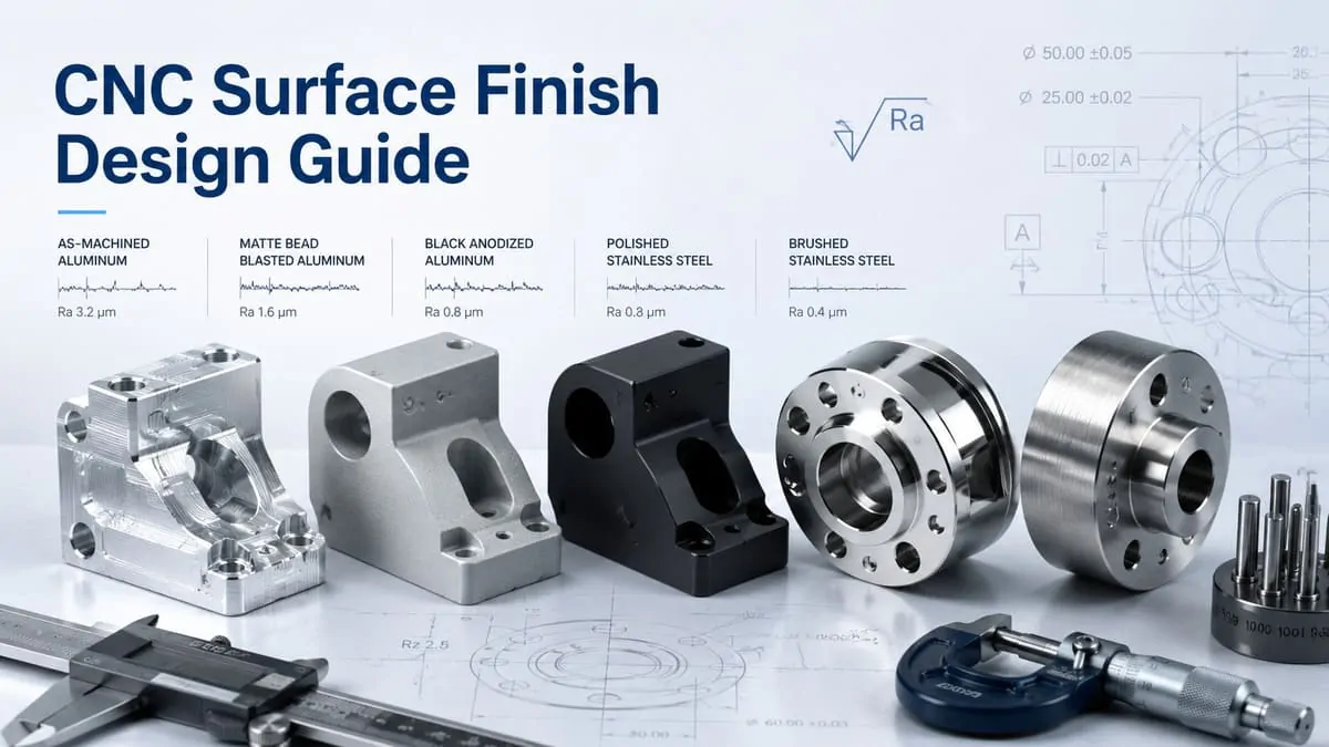
A common design mistake is applying the same surface finish requirement to every surface on a part. In many projects, only a few surfaces require controlled roughness or cosmetic consistency. Hidden areas, non-functional pockets, internal cavities, and clearance surfaces can often remain as-machined. By separating functional surfaces from cosmetic surfaces, engineers can improve part quality while avoiding unnecessary finishing cost.
This guide explains how to specify CNC surface finish requirements clearly and cost-effectively. It covers surface roughness, Ra values, as-machined finishes, cosmetic finishing, functional surfaces, common post-processing options, material compatibility, drawing callouts, tolerance impact, and supplier-side review.
If you need support with surface finish selection, material compatibility, tolerance impact, or manufacturability review, NAITE TECH provides custom CNC machining services for prototypes and production parts with engineering support for practical finishing requirements.
This guide covers practical CNC surface finish principles, helping engineers specify surface roughness, cosmetic finishes, coatings, and post-processing requirements without adding unnecessary machining or finishing cost.
Understand what surface finish means in CNC machining, including surface roughness, tool marks, lay direction, visual appearance, and functional surface quality.
Learn how Ra values are used to define surface roughness and when rough, standard, fine, or polished surfaces are appropriate for CNC machined parts.
Compare as-machined surfaces with bead blasting, anodizing, polishing, passivation, plating, powder coating, and other finishing processes.
Identify which surfaces affect sealing, friction, wear, assembly, or coating adhesion, and which surfaces mainly require cosmetic appearance control.
Review common finishing choices for CNC machined parts, including as-machined, bead blasted, anodized, hard anodized, polished, brushed, passivated, and plated finishes.
Understand how lower Ra values, cosmetic consistency, polishing, masking, coating thickness, inspection, and finishing lead time affect total part cost.
Learn how anodizing, plating, powder coating, polishing, and bead blasting can affect final dimensions, threads, edges, tight fits, and inspection requirements.
See how aluminum, stainless steel, brass, copper, titanium, and engineering plastics respond differently to surface finishing and post-processing.
Learn how to specify Ra values, cosmetic areas, coating thickness, masking requirements, and finish notes clearly on engineering drawings.
Surface finish in CNC machining refers to the texture, roughness, pattern, and appearance of a machined surface. It describes how smooth, rough, glossy, matte, directional, or tool-marked a surface is after machining or post-processing.
Surface finish can be controlled by the machining process itself, or it can be modified through additional finishing operations. For example, a part may be left as-machined, bead blasted for a matte appearance, anodized for corrosion resistance and color, polished for a smoother surface, or passivated to improve corrosion resistance on stainless steel.
In CNC machining, surface finish may include several related characteristics:
Surface roughness
Tool marks
Cutter path pattern
Lay direction
Gloss or matte appearance
Coating or anodized texture
Edge condition
Burr condition
Surface cleanliness
Functional contact quality
Surface finish should not be treated as a purely cosmetic detail. In many CNC machined parts, surface finish directly affects part performance.
For example:
A sealing surface may require controlled roughness to prevent leakage.
A sliding surface may need a smoother finish to reduce friction and wear.
A bearing-related surface may need a specific finish to support proper contact.
A cosmetic housing may need bead blasting and anodizing for consistent appearance.
A coated surface may need proper roughness for coating adhesion.
A threaded feature may need post-finish review to avoid assembly problems.
This is why surface finish requirements should be matched to the function of each surface.
For broader part design rules, you can also review NAITE TECH’s CNC machining design recommendations.
CNC surface finish can generally be divided into two categories: machined finish and post-processed finish.
Machined surface finish is created directly by the cutting tool. It depends on tool geometry, feed rate, spindle speed, step-over, material, cutting strategy, tool wear, and finishing passes. An as-machined surface may show visible tool marks, milling lines, turning marks, or cutter paths.
Post-processed surface finish is created after machining. This may include bead blasting, anodizing, polishing, brushing, passivation, plating, powder coating, painting, or other surface treatments. These processes can improve appearance, corrosion resistance, wear resistance, cleanliness, or surface texture.
A practical design should define whether the surface requirement is:
Functional
Cosmetic
Protective
Dimensional
Assembly-related
Coating-related
Inspection-related
For example, a visible aluminum enclosure may need bead blasting and black anodizing for appearance, while a bearing bore in the same part may need to be masked or controlled separately to maintain fit. Treating all surfaces the same can create avoidable cost or functional risk.
Surface finish affects several important design and manufacturing factors.
Surface Finish Factor | Why It Matters |
|---|---|
Appearance | Affects visible product quality and customer-facing surfaces |
Friction | Important for sliding, moving, or rotating interfaces |
Sealing | Surface roughness can affect leakage and gasket performance |
Wear resistance | Surface texture influences contact and wear behavior |
Coating adhesion | Some coatings require proper surface preparation |
Corrosion resistance | Finishes such as anodizing or passivation can improve protection |
Tolerance impact | Some finishes remove or add material |
Inspection | Roughness or cosmetic requirements may require additional checks |
Cost | Finer finishes and cosmetic requirements usually increase cost |
The key is to avoid over-specifying finish requirements. A sealing surface, visible cover, and hidden internal pocket may all need different finish strategies. Applying a fine Ra value or cosmetic finish to every surface can increase machining and post-processing cost without improving the final part.
Surface finish is often treated as a cosmetic requirement, but in CNC machining it can also affect sealing, friction, wear, coating adhesion, and assembly performance. Before production, NAITE TECH reviews whether each finish requirement is visual, functional, or both.
In many CNC projects, the most cost-effective approach is to define finish requirements by surface function. Critical sealing, sliding, or mating surfaces may need controlled roughness, while hidden or non-functional areas can often remain as-machined. This helps maintain part performance while avoiding unnecessary finishing cost.
Surface roughness is one of the most common ways to describe CNC surface finish. It measures the small peaks, valleys, and texture left on a surface after machining or finishing. In engineering drawings, surface roughness is often specified using an Ra value.
Ra, or arithmetic average roughness, represents the average height variation of a surface profile over a measured length. A lower Ra value usually means a smoother surface, while a higher Ra value means a rougher surface.
For example:
Ra 6.3 µm indicates a relatively rough machined surface.
Ra 3.2 µm is common for general machined surfaces.
Ra 1.6 µm is a finer machined finish.
Ra 0.8 µm or lower may be used for sealing, sliding, or precision contact surfaces.
However, Ra is only one way to describe surface finish. Two surfaces with the same Ra value may still look different if they have different tool marks, lay direction, polishing patterns, or coating textures. For this reason, surface finish requirements should consider both function and appearance.
The table below provides general surface roughness references for CNC machined parts. Actual results depend on material, geometry, tool condition, machining strategy, finishing process, and inspection method.
Surface Requirement | Typical Ra Range | Common Use |
|---|---|---|
Rough machined surface | Ra 6.3 µm or higher | Non-critical internal surfaces, roughing areas |
Standard machined finish | Ra 3.2 µm | General CNC machined parts |
Fine machined finish | Ra 1.6 µm | Visible surfaces, mating faces, improved appearance |
Precision surface | Ra 0.8 µm | Sealing, sliding, bearing-related, or contact surfaces |
Polished surface | Ra 0.4 µm or lower | Cosmetic, optical, low-friction, or special applications |
These values should be used as practical references, not universal rules. A surface roughness requirement that is easy to achieve on an open flat aluminum face may be more difficult on a deep pocket, thin wall, small internal radius, or hard material.
A lower Ra value is not always better. A smoother surface may improve sealing, sliding, or cosmetic appearance, but it can also increase machining time, finishing cost, and inspection requirements.
Lower Ra values may require:
Slower finishing passes
Smaller step-over
Sharper tools
More stable fixturing
Additional polishing
More inspection
Better tool wear control
More careful handling after finishing
If the surface does not affect function or appearance, specifying a very low Ra value may add cost without improving part performance.
For example, a hidden internal pocket does not usually need the same Ra value as a sealing face or sliding surface. A cosmetic exterior surface may require visual consistency, but not necessarily an extremely low roughness value. A bearing-related surface may need roughness control because it affects contact and wear.
The correct Ra value depends on the surface function.
Surface roughness and visual appearance are related, but they are not the same.
Ra measures surface texture numerically. Appearance describes how the surface looks to the eye. A surface may have an acceptable Ra value but still show visible tool marks, directional lines, color variation, blasting inconsistency, or polishing patterns.
This is especially important for customer-facing parts, such as:
Product housings
Consumer device components
Aluminum enclosures
Visible brackets
Medical device covers
Robotics covers
Optical equipment housings
For cosmetic parts, engineers should not rely only on Ra values. It is often better to specify the finish type, visible surfaces, color, gloss level, and acceptable cosmetic standard. Samples or reference photos can also help avoid misunderstanding.
Ra should be specified when surface roughness directly affects part function, performance, or inspection.
Common surfaces that may need an Ra callout include:
Sealing faces
Sliding surfaces
Bearing contact areas
Shaft surfaces
Mating surfaces
Fluid flow surfaces
Optical or sensor mounting surfaces
Precision datum surfaces
Surfaces prepared for coating or bonding
Not every surface needs an Ra value. If no specific surface roughness is required, it may be enough to use a general note such as “as machined” or define a standard finish for non-critical areas.
A practical drawing may include:
General finish note for most surfaces
Specific Ra value only for functional surfaces
Cosmetic finish note for visible surfaces
Masking notes for threads, bores, or tight-fit areas
Coating or anodizing requirements when needed
This approach gives the supplier clear instructions without making every surface expensive to machine or inspect.
Surface roughness requirements affect cost because smoother surfaces usually require more controlled machining or post-processing.
Cost increases when:
A lower Ra value is required
More surfaces need controlled roughness
The surface is deep or hard to access
Small tools are required
Polishing is required
Cosmetic consistency is required
Inspection reports are required
The finish must be protected during handling
Coating or masking is needed after machining
For this reason, surface roughness should be applied selectively. The goal is to specify the surface quality the part actually needs, not the lowest possible Ra value.
If your part has surface finish requirements that may affect tolerance, assembly, or cost, NAITE TECH can provide CNC surface finish review before production.
One common cost driver is specifying a fine Ra value on every surface. In many CNC parts, only sealing faces, sliding surfaces, bearing-related areas, or visible cosmetic surfaces need controlled roughness. Non-critical or hidden surfaces can often remain as-machined.
During surface finish review, NAITE TECH evaluates whether each Ra requirement is functional, cosmetic, or unnecessary. This helps reduce machining and inspection cost while keeping the surfaces that matter properly controlled.Surface Roughness and Ra Values Explained
Surface roughness is one of the most common ways to describe CNC surface finish. It measures the small peaks, valleys, and texture left on a surface after machining or finishing. In engineering drawings, surface roughness is often specified using an Ra value.
Ra, or arithmetic average roughness, represents the average height variation of a surface profile over a measured length. A lower Ra value usually means a smoother surface, while a higher Ra value means a rougher surface.
For example:
Ra 6.3 µm indicates a relatively rough machined surface.
Ra 3.2 µm is common for general machined surfaces.
Ra 1.6 µm is a finer machined finish.
Ra 0.8 µm or lower may be used for sealing, sliding, or precision contact surfaces.
However, Ra is only one way to describe surface finish. Two surfaces with the same Ra value may still look different if they have different tool marks, lay direction, polishing patterns, or coating textures. For this reason, surface finish requirements should consider both function and appearance.
The table below provides general surface roughness references for CNC machined parts. Actual results depend on material, geometry, tool condition, machining strategy, finishing process, and inspection method.
Surface Requirement | Typical Ra Range | Common Use |
|---|---|---|
Rough machined surface | Ra 6.3 µm or higher | Non-critical internal surfaces, roughing areas |
Standard machined finish | Ra 3.2 µm | General CNC machined parts |
Fine machined finish | Ra 1.6 µm | Visible surfaces, mating faces, improved appearance |
Precision surface | Ra 0.8 µm | Sealing, sliding, bearing-related, or contact surfaces |
Polished surface | Ra 0.4 µm or lower | Cosmetic, optical, low-friction, or special applications |
These values should be used as practical references, not universal rules. A surface roughness requirement that is easy to achieve on an open flat aluminum face may be more difficult on a deep pocket, thin wall, small internal radius, or hard material.
A lower Ra value is not always better. A smoother surface may improve sealing, sliding, or cosmetic appearance, but it can also increase machining time, finishing cost, and inspection requirements.
Lower Ra values may require:
Slower finishing passes
Smaller step-over
Sharper tools
More stable fixturing
Additional polishing
More inspection
Better tool wear control
More careful handling after finishing
If the surface does not affect function or appearance, specifying a very low Ra value may add cost without improving part performance.
For example, a hidden internal pocket does not usually need the same Ra value as a sealing face or sliding surface. A cosmetic exterior surface may require visual consistency, but not necessarily an extremely low roughness value. A bearing-related surface may need roughness control because it affects contact and wear.
The correct Ra value depends on the surface function.
Surface roughness and visual appearance are related, but they are not the same.
Ra measures surface texture numerically. Appearance describes how the surface looks to the eye. A surface may have an acceptable Ra value but still show visible tool marks, directional lines, color variation, blasting inconsistency, or polishing patterns.
This is especially important for customer-facing parts, such as:
Product housings
Consumer device components
Aluminum enclosures
Visible brackets
Medical device covers
Robotics covers
Optical equipment housings
For cosmetic parts, engineers should not rely only on Ra values. It is often better to specify the finish type, visible surfaces, color, gloss level, and acceptable cosmetic standard. Samples or reference photos can also help avoid misunderstanding.
Ra should be specified when surface roughness directly affects part function, performance, or inspection.
Common surfaces that may need an Ra callout include:
Sealing faces
Sliding surfaces
Bearing contact areas
Shaft surfaces
Mating surfaces
Fluid flow surfaces
Optical or sensor mounting surfaces
Precision datum surfaces
Surfaces prepared for coating or bonding
Not every surface needs an Ra value. If no specific surface roughness is required, it may be enough to use a general note such as “as machined” or define a standard finish for non-critical areas.
A practical drawing may include:
General finish note for most surfaces
Specific Ra value only for functional surfaces
Cosmetic finish note for visible surfaces
Masking notes for threads, bores, or tight-fit areas
Coating or anodizing requirements when needed
This approach gives the supplier clear instructions without making every surface expensive to machine or inspect.
Surface roughness requirements affect cost because smoother surfaces usually require more controlled machining or post-processing.
Cost increases when:
A lower Ra value is required
More surfaces need controlled roughness
The surface is deep or hard to access
Small tools are required
Polishing is required
Cosmetic consistency is required
Inspection reports are required
The finish must be protected during handling
Coating or masking is needed after machining
For this reason, surface roughness should be applied selectively. The goal is to specify the surface quality the part actually needs, not the lowest possible Ra value.
If your part has surface finish requirements that may affect tolerance, assembly, or cost, NAITE TECH can provide CNC surface finish review before production.
One common cost driver is specifying a fine Ra value on every surface. In many CNC parts, only sealing faces, sliding surfaces, bearing-related areas, or visible cosmetic surfaces need controlled roughness. Non-critical or hidden surfaces can often remain as-machined.
During surface finish review, NAITE TECH evaluates whether each Ra requirement is functional, cosmetic, or unnecessary. This helps reduce machining and inspection cost while keeping the surfaces that matter properly controlled.
An as-machined surface finish is the surface condition left directly by the CNC cutting process, without additional post-processing such as bead blasting, anodizing, polishing, plating, or painting. It is one of the most common and cost-effective finish options for CNC machined parts.
As-machined surfaces may show visible tool marks, milling paths, turning lines, cutter step-over patterns, or slight directional texture. The appearance depends on the machining process, tool condition, cutting parameters, material, and finishing pass strategy.
For many mechanical parts, an as-machined finish is fully acceptable. It provides a functional surface while avoiding the additional cost, lead time, and dimensional risks of secondary finishing.
An as-machined surface usually has a clean metallic or plastic surface with visible machining marks. These marks are created by the cutting tool as it removes material.
Common visual characteristics include:
Milling tool paths
Turning lines
Directional machining marks
Slight step-over patterns
Tool entry or exit marks
Sharp machined edges before deburring
Surface texture based on cutting parameters
The surface can still be clean and professional, but it will not usually have the uniform matte appearance of bead blasting or the glossy appearance of polishing.
If a part needs a consistent cosmetic surface, as-machined may not be enough. If the part is mainly functional and tool marks are acceptable, as-machined is often the most efficient option.
As-machined finish is suitable when surface appearance is not the main requirement or when the part’s function does not require additional surface treatment.
It is often a good choice for:
Functional prototypes
Internal mechanical components
Hidden surfaces
Fixtures and tooling
Brackets
Mounting plates
Machine components
Test parts
Engineering validation parts
Cost-sensitive production parts
As-machined finish is especially useful when the goal is to validate geometry, fit, assembly, or mechanical performance before adding cosmetic or protective finishing.
For prototypes, using as-machined finish can reduce lead time and help engineers test the part faster.
As-machined finish may not be suitable when the part requires a specific appearance, corrosion protection, wear resistance, low friction, or controlled surface roughness.
Additional finishing may be needed for:
Customer-facing cosmetic parts
Aluminum parts requiring anodizing
Stainless steel parts requiring passivation
Parts exposed to moisture or corrosive environments
Sliding surfaces requiring lower roughness
Sealing surfaces requiring controlled finish
Parts requiring color or branding appearance
Medical or food-related components needing cleaner surfaces
Components requiring improved wear resistance
For example, an aluminum enclosure may be functional as-machined, but it may need bead blasting and anodizing to achieve a uniform matte black appearance. A stainless steel component may be machined accurately, but still require passivation for improved corrosion resistance.
As-machined surface roughness depends on several machining factors:
Tool sharpness
Feed rate
Step-over
Cutting speed
Tool path strategy
Material type
Tool wear
Finishing pass depth
Machine rigidity
Coolant and chip evacuation
A standard as-machined finish may be acceptable for many general surfaces. However, if a specific Ra value is required, it should be called out on the drawing.
For example:
A hidden pocket may be acceptable as-machined.
A visible cover may need bead blasting or brushing.
A sealing surface may need a controlled Ra value.
A sliding surface may need a smoother finishing pass or polishing.
A bearing-related surface may need a specific roughness and dimensional tolerance.
The drawing should define which surfaces require controlled finish and which surfaces can remain as-machined.
Even when a part is specified as as-machined, basic deburring is usually important. Sharp edges, burrs, and tool exit marks can affect handling, assembly, safety, and appearance.
A practical drawing note may include:
“As machined, deburr all sharp edges”
“Break sharp edges 0.2–0.5 mm”
“Remove burrs before inspection”
“No loose burrs allowed”
“Maintain sharp edges only where specified”
Deburring should be defined carefully because aggressive deburring can change edge dimensions, affect sealing edges, or damage small features. If an edge must remain sharp, it should be clearly marked.
As-machined finish is usually the lowest-cost surface option because it avoids additional finishing processes. However, the cost can still increase if a very smooth as-machined Ra value is required.
Cost may increase when:
Very fine toolpaths are required
Small step-over is needed
Additional finishing passes are required
Every surface needs a controlled Ra value
Deep pockets require clean tool marks
Small internal radii require small tools
Cosmetic tool mark direction must be controlled
Inspection reports are required for surface roughness
This is why “as-machined” should not be confused with “any surface quality.” If an as-machined surface needs a specific Ra value or visual standard, that requirement should be clearly stated.
As-machined finish is often the best starting point for CNC prototypes and non-cosmetic mechanical parts. It helps reduce cost and lead time while keeping the focus on geometry, tolerance, fit, and function.
However, as-machined does not mean uncontrolled. If a surface affects sealing, sliding, bearing contact, coating adhesion, or visible product quality, NAITE TECH recommends defining that requirement clearly on the drawing. This allows the machining process to focus finishing effort only where it creates functional or cosmetic value.
Not every surface on a CNC machined part has the same purpose. Some surfaces affect how the part performs, while others mainly affect how the part looks. A cost-effective surface finish strategy starts by separating functional surface requirements from cosmetic surface requirements.
Functional surfaces should be specified with measurable requirements such as surface roughness, flatness, coating thickness, wear resistance, or sealing performance. Cosmetic surfaces should be specified with appearance-related requirements such as color, texture, gloss, visible tool marks, or finish consistency.
When these two requirements are mixed together, parts can become more expensive than necessary. A visible exterior surface may need a consistent bead blasted and anodized appearance, but it may not need a very low Ra value. A sealing surface may need controlled roughness, but it may not need cosmetic polishing.
A functional surface finish affects the performance of the part. It may influence sealing, sliding, friction, wear, assembly fit, coating adhesion, electrical contact, fluid flow, or dimensional stability.
Functional surface finish requirements are common on:
Sealing faces
Gasket contact surfaces
Sliding surfaces
Bearing-related surfaces
Shaft contact areas
Mating faces
Datum surfaces
Fluid flow passages
Threaded interfaces
Electrical contact surfaces
Bonding or coating surfaces
Precision assembly interfaces
For these surfaces, the finish requirement should be based on how the part works. A sealing surface may need a specific Ra value. A sliding surface may need lower roughness to reduce friction. A bonding surface may need proper texture for adhesion. A coated surface may need preparation before plating, anodizing, or painting.
Functional requirements should be clear, measurable, and limited to the surfaces that actually need them.
A cosmetic surface finish mainly affects appearance and user perception. It is important for parts that are visible to customers, assembled into finished products, or used in applications where visual quality matters.
Cosmetic finish requirements are common on:
Product housings
Aluminum enclosures
Consumer device components
Visible brackets
Front panels
Medical device covers
Robotics covers
Display parts
Camera or optical equipment housings
Customer-facing hardware
Cosmetic surface finish may include:
Bead blasted matte texture
Brushed grain direction
Polished surface appearance
Anodized color
Powder coated color
Painted surface quality
Uniform gloss level
No visible tool marks on exposed surfaces
No scratches or handling marks on visible faces
Cosmetic requirements are often harder to judge by numbers alone. A surface may meet an Ra value but still look unacceptable because of inconsistent tool marks, color variation, polishing direction, or blasting pattern. For cosmetic surfaces, reference samples, photos, or clear visual standards can help avoid misunderstanding.
Some surfaces are both functional and cosmetic. For example, an exposed aluminum housing may need a uniform anodized appearance, while also maintaining accurate flatness on a mounting face. A stainless steel medical part may need a clean visual finish and corrosion-resistant passivation. A sliding cover may need both smooth motion and consistent appearance.
When a surface has both functional and cosmetic requirements, the drawing should define both clearly.
For example:
Visible surface: bead blast + black anodize
Sealing surface: Ra 0.8 µm, mask before anodizing if needed
Bearing bore: maintain final dimension after finish
Threaded holes: mask or inspect after coating
Cosmetic face: no visible tool marks after finishing
This helps the supplier understand which surfaces must be protected, masked, inspected, or finished differently.
Separating functional and cosmetic surface requirements helps reduce cost because it prevents unnecessary finishing on surfaces that do not need it.
For example:
Surface Type | Poor Finish Strategy | Better Finish Strategy |
|---|---|---|
Hidden internal pocket | Fine Ra and cosmetic finish | As-machined unless function-critical |
Sealing face | Same cosmetic finish as exterior | Controlled Ra and flatness if required |
Visible exterior cover | Very low Ra specified | Bead blast or brush for visual consistency |
Bearing bore | Anodized without review | Mask or control final dimension after finish |
Threaded holes | Coated without fit check | Mask or inspect thread fit after finishing |
Cosmetic chamfers | Tight finish and size control | Standard edge break with visual acceptance |
This approach keeps important surfaces controlled while reducing unnecessary polishing, blasting, coating, inspection, or masking.
A clear drawing should tell the supplier which surfaces require functional finish control and which surfaces require cosmetic appearance control.
Useful drawing methods include:
Surface roughness symbols for functional surfaces
Finish notes for visible cosmetic surfaces
Masking notes for threads, bores, and tight-fit areas
Coating thickness notes when final dimensions matter
Different finish zones for visible and hidden areas
Datum references for surfaces that affect inspection
Notes such as “cosmetic surface” or “visible surface”
Notes such as “as-machined unless otherwise specified”
Example drawing notes:
“Visible exterior surfaces: bead blast + clear anodize”
“Internal pockets: as-machined unless otherwise specified”
“Sealing face: Ra 0.8 µm”
“Mask bearing bore before anodizing”
“Do not coat threaded holes”
“Remove burrs, break sharp edges 0.2–0.5 mm”
“No visible tool marks on front face”
Clear finish zones reduce supplier assumptions and help prevent unnecessary cost.
One common mistake is using a low Ra value to control appearance. While Ra measures roughness, it does not fully define visual quality.
A part may have a low Ra value but still show:
Directional machining marks
Uneven polishing
Color variation after anodizing
Inconsistent bead blasting
Handling scratches
Toolpath transitions
Visible cutter marks
For cosmetic parts, finish type and visual standard often matter more than Ra alone. A bead blasted and anodized surface may look more consistent than a low-Ra machined surface, even if the Ra value is not extremely low.
If appearance matters, specify the desired finish process and visible surfaces clearly.
In many CNC projects, unnecessary cost comes from applying cosmetic or fine surface finish requirements to every surface instead of limiting them to visible or functional areas. A hidden pocket, clearance cutout, or internal cavity usually does not need the same finish as an exposed product surface or sealing face.
Before production, NAITE TECH reviews surface finish requirements by function. We evaluate which surfaces affect sealing, sliding, wear, coating adhesion, assembly, or appearance, and where as-machined finish is sufficient. This helps reduce finishing cost while keeping critical and visible surfaces properly controlled.
CNC machined parts can be finished in many different ways depending on material, appearance, function, corrosion resistance, wear resistance, and cost requirements. Some parts can remain as-machined, while others may need bead blasting, anodizing, polishing, brushing, passivation, plating, powder coating, or painting.
The best surface finish is not always the smoothest or most expensive option. The best finish is the one that matches the part’s function, environment, appearance requirement, tolerance requirement, and production budget.
An as-machined finish is the surface left directly by the CNC cutting process. It may show tool marks, cutter paths, turning lines, or directional machining patterns.
As-machined finish is often the most cost-effective choice because it does not require secondary finishing.
Best for:
Functional prototypes
Hidden surfaces
Internal mechanical parts
Fixtures and tooling
Cost-sensitive components
Parts where tool marks are acceptable
Advantages:
Lowest finishing cost
Shorter lead time
No coating thickness impact
Good for engineering validation
Suitable for many mechanical components
Limitations:
Visible tool marks may remain
Appearance may not be uniform
Limited corrosion protection
Not ideal for customer-facing cosmetic parts
A drawing note such as “as machined, deburr all sharp edges” is often suitable for non-cosmetic CNC parts.
Bead blasting uses fine media to create a uniform matte surface texture. It is commonly used on aluminum and stainless steel parts to reduce visible machining marks and create a cleaner cosmetic appearance.
Bead blasting is often used before anodizing to improve visual consistency.
Best for:
Aluminum enclosures
Product housings
Visible brackets
Robotics components
Medical device covers
Cosmetic machined parts
Parts requiring uniform matte texture
Advantages:
Creates consistent matte appearance
Reduces visible tool marks
Suitable before anodizing
Good for customer-facing parts
Moderate cost compared with polishing
Limitations:
May slightly affect sharp edges
May not reach deep internal features uniformly
Can change surface texture
Requires care for tight tolerance features
May need masking for critical bores or threads
If cosmetic consistency matters, define which surfaces should be bead blasted and which surfaces can remain as-machined.
Anodizing is an electrochemical finishing process commonly used for aluminum parts. It improves corrosion resistance, surface hardness, and appearance. Anodizing can be clear, black, or colored depending on the requirement.
Anodizing is one of the most common finishing options for CNC machined aluminum parts.
Best for:
Aluminum housings
Enclosures
Brackets
Consumer product components
Robotics parts
Aerospace components
Electronic device parts
Parts requiring color and corrosion resistance
Advantages:
Improves corrosion resistance
Provides decorative color options
Improves surface hardness
Works well with bead blasting
Common for aluminum CNC parts
Limitations:
Adds or changes surface thickness
Color may vary slightly between batches
Threads and tight bores may need masking
Sharp edges may show different color density
Not suitable for all aluminum alloys equally
Anodizing should be reviewed together with tolerance requirements. If a bore, thread, or fit is critical, specify whether it should be masked, machined after anodizing, or inspected after finishing.
Hard anodizing is a thicker and more wear-resistant anodizing process. It is commonly used when aluminum parts require improved durability, wear resistance, or surface hardness.
Best for:
Wear surfaces
Sliding components
Aerospace parts
Industrial machine components
Aluminum parts exposed to friction
Components requiring stronger surface protection
Advantages:
Higher surface hardness than standard anodizing
Better wear resistance
Improved durability
Good for functional aluminum components
Better protection in demanding environments
Limitations:
Thicker coating may affect dimensions
Color options may be more limited
May increase cost
Masking may be required for tight tolerance features
Surface appearance may be less decorative than standard anodizing
Hard anodizing should be specified carefully when final dimensions, bores, threads, or sliding fits are important.
Polishing reduces surface roughness and can create a smoother, brighter, or more reflective surface. It is often used for cosmetic parts, low-friction applications, and components requiring smoother contact surfaces.
Best for:
Cosmetic metal parts
Stainless steel components
Aluminum decorative parts
Brass components
Low-friction surfaces
Medical or cleanability-related parts
Special appearance requirements
Advantages:
Improves smoothness
Can reduce visible tool marks
Enhances cosmetic appearance
May improve cleanability
Can support lower roughness requirements
Limitations:
Labor-intensive
Higher cost
May round sharp edges
May affect dimensions
Difficult inside deep pockets or small internal corners
Appearance depends on material and geometry
Polishing should not be applied automatically to every surface. It is best used only where smoothness or appearance is functionally or cosmetically required.
Brushing creates a directional grain pattern on a metal surface. It is commonly used for decorative aluminum or stainless steel parts where a consistent linear texture is desired.
Best for:
Visible panels
Consumer product parts
Decorative metal surfaces
Aluminum enclosures
Stainless steel covers
Front plates and faceplates
Advantages:
Creates controlled directional appearance
Reduces random visual tool marks
Good for customer-facing surfaces
Provides a premium cosmetic texture
Limitations:
Direction must be specified
Not ideal for complex geometry
Can be difficult around holes, pockets, and edges
May not be uniform on small or irregular features
Can add manual finishing cost
If brushing is required, the drawing should define the grain direction and visible surfaces.
Passivation is commonly used for stainless steel parts to improve corrosion resistance by removing free iron and enhancing the protective oxide layer. It does not create a thick coating like plating or painting.
Best for:
Stainless steel machined parts
Medical components
Food processing components
Corrosion-resistant hardware
Fluid handling parts
Clean mechanical components
Advantages:
Improves corrosion resistance
Maintains stainless steel appearance
Does not significantly change dimensions
Good for clean or corrosion-sensitive applications
Common for stainless steel components
Limitations:
Does not hide machining marks
Does not create decorative color
Material grade and surface condition matter
Requires cleaning before processing
May not solve corrosion issues caused by poor material selection
Passivation is often a good choice when stainless steel parts need improved corrosion resistance without changing dimensions significantly.
Electropolishing is an electrochemical process that smooths and brightens stainless steel surfaces by removing a thin layer of material. It can improve cleanability, corrosion resistance, and surface smoothness.
Best for:
Stainless steel medical parts
Food and beverage components
Cleanroom hardware
Fluid path components
Parts requiring smooth and clean surfaces
Corrosion-sensitive stainless steel parts
Advantages:
Improves surface smoothness
Enhances cleanability
Can improve corrosion resistance
Reduces microscopic surface peaks
Suitable for hygiene-sensitive applications
Limitations:
Removes material
May affect sharp edges
Not ideal for all geometries
Cost is higher than simple passivation
Critical dimensions must be reviewed before processing
Electropolishing should be considered when cleanability and corrosion resistance are more important than simple appearance.
Plating applies a metal coating to the surface of a part. Common options include nickel plating, zinc plating, chrome plating, tin plating, and other specialized coatings depending on the application.
Best for:
Steel components requiring corrosion protection
Brass and copper parts
Electrical contacts
Wear-resistant surfaces
Decorative metal parts
Conductive or solderable surfaces
Advantages:
Can improve corrosion resistance
Can improve wear resistance
Can improve conductivity
Can provide decorative appearance
Wide range of coating options
Limitations:
Adds coating thickness
May affect threads, bores, and fits
May require masking
Coating uniformity depends on geometry
Process selection depends on material and application
When plating is used, coating thickness and final dimensions should be reviewed carefully.
Powder coating and painting are commonly used when parts need color, environmental protection, or brand appearance. These finishes are thicker than anodizing and can significantly affect dimensions if applied to precision features.
Best for:
Enclosures
Covers
Frames
Brackets
Industrial equipment parts
Outdoor components
Customer-facing products requiring color
Advantages:
Good color options
Good environmental protection
Can cover machining marks
Useful for larger parts
Suitable for brand or product appearance
Limitations:
Adds significant thickness
Can affect hole sizes, threads, and fits
May require masking
Not suitable for tight tolerance surfaces unless controlled
Can chip or scratch depending on use
Powder coating and painting should be specified with masking requirements if threads, bores, sealing faces, or precision mating surfaces must remain controlled.
Finish Option | Common Materials | Main Purpose | Cost Impact |
|---|---|---|---|
As-machined | Metals and plastics | Basic functional surface | Low |
Bead blasting | Aluminum, stainless steel | Uniform matte cosmetic texture | Medium |
Anodizing | Aluminum | Corrosion resistance, color, appearance | Medium |
Hard anodizing | Aluminum | Wear resistance and durability | Medium to high |
Polishing | Aluminum, stainless steel, brass | Smooth or glossy surface | High |
Brushing | Aluminum, stainless steel | Directional cosmetic grain | Medium to high |
Passivation | Stainless steel | Corrosion resistance | Medium |
Electropolishing | Stainless steel | Cleanability, smoothness, corrosion resistance | High |
Plating | Steel, brass, copper alloys | Protection, conductivity, wear resistance | Medium to high |
Powder coating / painting | Aluminum, steel | Color and environmental protection | Medium |
The best CNC surface finish depends on the part’s material, function, geometry, tolerance requirements, and visual expectations. A finish that works well for an exterior aluminum housing may not be suitable for a bearing bore, threaded hole, sealing surface, or precision-fit feature.
Before production, NAITE TECH reviews finishing requirements together with machining tolerances, material selection, masking needs, and inspection requirements. This helps avoid common problems such as coating buildup in threads, anodizing thickness on tight bores, polishing that changes edges, or unnecessary cosmetic finishing on hidden surfaces.
Surface finish can have a significant impact on CNC machining cost. A basic as-machined finish may add little or no extra cost, while a fine Ra requirement, polished surface, cosmetic bead blasting, anodizing, plating, or powder coating can increase both production time and process complexity.
The cost of surface finish depends on more than the finishing method itself. It is also affected by how many surfaces require finishing, how difficult those surfaces are to access, whether the finish changes dimensions, whether masking is required, and whether cosmetic or inspection standards must be controlled.
A cost-effective surface finish strategy applies special finish requirements only where they are needed for function, appearance, corrosion resistance, wear resistance, or assembly.
Lower Ra values usually require more careful machining. A standard machined surface may be produced with normal finishing passes, but a smoother surface may require slower cutting parameters, smaller step-over, sharper tools, more stable fixturing, or additional finishing passes.
This increases cost because the machine spends more time on each part.
Lower Ra values may require:
Slower feed rates
Smaller step-over
Additional finishing passes
More careful tool wear control
More stable workholding
Better vibration control
More detailed inspection
If a low Ra value is required only on one sealing surface, the cost impact may be manageable. If the same low Ra value is applied to every surface, machining cost can increase quickly.
The number of surfaces requiring finish control directly affects cost. Finishing one visible exterior face is very different from finishing every pocket, side wall, internal cavity, hole, and edge.
Cost increases when finish requirements apply to:
Multiple faces
Deep pockets
Small internal features
Thin walls
Complex contours
Tight internal corners
Holes and threaded areas
Areas that require masking
Surfaces that need inspection reports
Even if the finish process is simple, more finished surfaces require more handling, more preparation, and more inspection.
A clear drawing should identify which surfaces need special finish and which can remain as-machined. This prevents the supplier from assuming that every surface needs the same treatment.
Polishing can significantly increase cost because it often requires manual or semi-manual work. The final result depends on material, geometry, access, edge condition, and operator consistency.
Polishing is more expensive when:
The surface area is large
Internal pockets must be polished
Small radii are involved
Sharp edges must be preserved
A mirror-like finish is required
Cosmetic consistency is critical
Multiple polishing steps are needed
The material is difficult to polish
Polishing can also affect dimensions and edge geometry. It may round sharp edges, slightly remove material, or change the surface profile. For tight tolerance features, polishing should be reviewed before production.
Bead blasting is often less expensive than polishing, but it still adds cost. The part must be cleaned, blasted, handled carefully, and sometimes protected before the next finishing step such as anodizing.
Cosmetic bead blasting can increase cost when:
Only selected surfaces should be blasted
Certain features need masking
Uniform appearance is required
Deep pockets or complex geometry are involved
Parts must match a sample or previous batch
Handling marks are not acceptable
The part requires anodizing after blasting
Bead blasting can reduce visible tool marks, but it may not create identical results on every geometry. Deep pockets, narrow slots, and internal features may not receive the same blasting texture as open exterior surfaces.
Some surface treatments add material, remove material, or change the surface condition. This can affect final dimensions, fits, threads, and tolerances.
Examples include:
Anodizing can change surface thickness.
Hard anodizing can add more significant coating thickness.
Plating adds material to the surface.
Powder coating and painting add relatively thick layers.
Polishing removes material.
Electropolishing removes a thin layer of material.
Bead blasting changes texture and may affect sharp edges.
If a feature has a tight fit, such as a bearing bore, dowel pin hole, shaft diameter, sealing groove, or threaded hole, the finish effect must be considered before production.
In some cases, critical features should be masked before finishing, machined after finishing, or inspected after finishing.
Masking is used to protect selected areas from finishing. It may be required when coating, anodizing, blasting, painting, or plating should not affect certain features.
Masking may be needed for:
Threads
Bearing bores
Dowel pin holes
Press-fit holes
Sealing faces
Electrical contact areas
Datum surfaces
Grounding surfaces
Areas requiring bare metal contact
Masking adds cost because it requires additional preparation, manual work, process control, and inspection. Complex masking requirements can also increase lead time.
To reduce cost, only specify masking where it is functionally necessary.
Cosmetic finish requirements can increase cost because appearance is often more subjective than dimensional tolerance. A part may be dimensionally correct but still rejected because of scratches, uneven color, visible tool marks, blasting inconsistency, or handling marks.
Cosmetic risk increases when:
Surfaces are large and visible
Anodized color must match tightly
Polishing direction must be consistent
Brushing grain direction matters
Parts must match previous batches
Sharp edges show coating variation
Handling scratches are not acceptable
Cosmetic requirements are not clearly defined
For cosmetic CNC parts, drawings should define visible surfaces, acceptable appearance standards, color expectations, and finish samples if possible.
Secondary finishing can add lead time after machining. Some finishes require cleaning, masking, batch processing, inspection, drying, curing, or outside vendor coordination.
Lead time may increase with:
Anodizing
Hard anodizing
Plating
Powder coating
Painting
Electropolishing
Complex polishing
Special cosmetic requirements
Inspection reports after finishing
If schedule is important, finishing requirements should be discussed before production.
A practical way to reduce finishing cost is to define finish requirements by surface function.
Surface or Requirement | Cost-Saving Strategy |
|---|---|
Hidden internal surfaces | Leave as-machined unless function-critical |
Visible exterior faces | Specify cosmetic finish only where visible |
Sealing surfaces | Specify Ra only on the sealing area |
Bearing bores | Review finish thickness and masking needs |
Threads | Mask or inspect after finishing if fit matters |
Deep pockets | Avoid polishing unless functionally required |
Cosmetic color | Use samples or clear color references |
Tight tolerance features | Review final dimensions after finish |
Large surfaces | Avoid unnecessary low Ra requirements |
Prototype parts | Use as-machined finish when appearance is not critical |
A finish requirement should answer a clear question:
Does this surface need a special finish for function, appearance, protection, or assembly?
If the answer is no, as-machined or standard finishing may be enough.
Surface finish cost is often driven by scope, not only by finish type. A bead blasted or anodized exterior surface may be reasonable, but requiring the same finish inside deep pockets, threaded holes, hidden cavities, or tight tolerance bores can create unnecessary cost and risk.
During surface finish review, NAITE TECH evaluates which surfaces need functional roughness, cosmetic appearance, corrosion protection, masking, or post-finish inspection. This helps engineers specify the right finish in the right areas while avoiding unnecessary machining and finishing cost.
For projects where surface finish affects tolerance, appearance, or assembly, NAITE TECH’s CNC surface finish review can help identify practical finishing strategies before production.
Surface finish and CNC tolerances should be considered together. A part may be machined within tolerance before finishing, but the final dimensions can change after anodizing, plating, powder coating, polishing, bead blasting, or electropolishing. If these effects are not considered during design, the finished part may have fit, assembly, sealing, or inspection problems.
This is especially important for tight tolerance features such as bearing bores, dowel pin holes, threaded holes, press-fit holes, sliding surfaces, sealing grooves, and precision mating faces. These features may need masking, post-finish inspection, or adjusted machining dimensions to achieve the correct final result.
Different finishing processes affect dimensions in different ways. Some finishes add material to the surface, while others remove material or change the surface texture.
Examples include:
Anodizing can change surface thickness on aluminum parts.
Hard anodizing usually creates a thicker and more wear-resistant layer.
Plating adds a metallic coating to the surface.
Powder coating and painting add relatively thick layers.
Polishing removes material and may round edges.
Electropolishing removes a thin layer of metal.
Bead blasting changes surface texture and may slightly affect edges.
If a drawing only defines the machined dimension but does not consider the finish, the final part may not meet the intended fit.
For example, a bearing bore that is correct before anodizing may become too small if the anodized layer is applied to the bore. A threaded hole may become tight if coating builds up inside the thread. A press-fit hole may not assemble correctly if plating thickness is not considered.
Any feature that controls fit or movement should be reviewed before the finishing process is selected.
Critical features may include:
Bearing bores
Dowel pin holes
Shaft diameters
Press-fit holes
Slip-fit holes
Threaded holes
Sealing grooves
Sliding surfaces
Datum surfaces
Electrical contact areas
Grounding surfaces
For these features, the design team and machining supplier should decide whether the feature should be finished, masked, machined after finishing, or inspected after finishing.
A practical drawing note might say:
“Mask bearing bore before anodizing”
“Do not coat threaded holes”
“Final dimension applies after plating”
“Ra 0.8 µm on sealing face only”
“Maintain electrical contact surface uncoated”
“Inspect thread fit after coating”
These notes help prevent fit-related problems after finishing.
When a coating or finish adds thickness, the final dimension may differ from the machined dimension. This is especially important for holes, bores, shafts, slots, threads, and mating surfaces.
For external features, coating buildup may increase the final dimension. For internal features such as holes or bores, coating buildup may reduce the effective opening. This can affect clearance, press fit, thread fit, and sliding movement.
Designers should clarify whether a tolerance applies:
Before finishing
After finishing
To masked areas
To coated areas
To final assembled condition
If this is not clear, the supplier may need to make assumptions, which can increase quotation uncertainty or production risk.
For tolerance-sensitive parts, NAITE TECH’s CNC machining tolerance review can help evaluate how finishing may affect final part dimensions.
Polishing can improve surface smoothness and appearance, but it may also change edge geometry. Sharp edges may become rounded, small details may lose definition, and precision surfaces may shift slightly if too much material is removed.
This matters for:
Sealing edges
Sharp locating edges
Small chamfers
Precision slots
Cosmetic edges
Thin features
Datum surfaces
Parts with tight profile requirements
If a part requires both polishing and tight edge definition, the drawing should clearly define which edges can be softened and which must remain controlled.
A useful note may be:
“Polish visible surface only; maintain sharp functional edges”
“Do not polish datum surface”
“Protect sealing edge during polishing”
“Break sharp edges except where specified”
Bead blasting usually does not add a thick coating, but it changes the surface texture. It can reduce visible tool marks and create a uniform matte appearance, but it may also slightly soften edges or affect very small features.
Bead blasting can be a good cosmetic solution for visible aluminum parts, especially before anodizing. However, it should be reviewed carefully when the part includes:
Tight tolerance bores
Precision holes
Fine threads
Sealing surfaces
Sharp edges
Small text or engraved markings
Very thin features
If these areas must remain precise or sharp, masking may be required.
Threaded features are especially sensitive to finishing. Coatings or anodizing inside threads can change fit and make fastener assembly difficult. Polishing, blasting, or plating can also affect thread quality if not controlled.
Thread finishing risks include:
Coating buildup
Tight thread fit
Damaged thread crests
Poor gauge results
Difficult fastener installation
Inconsistent torque
Corrosion risk if threads are masked incorrectly
For threaded features, engineers should specify whether threads should be coated, masked, cleaned, chased, or inspected after finishing.
For more guidance on thread design and fastener fit, review NAITE TECH’s threaded hole finishing considerations.
Internal features are more difficult to finish consistently than open exterior surfaces. Coating thickness, blasting access, polishing tools, and inspection tools may all behave differently inside holes or bores.
Important internal features include:
Bearing bores
Dowel pin holes
Reamed holes
Press-fit holes
Deep holes
Counterbores
Sealing grooves
Internal pockets
Fluid passages
If an internal feature has a tight tolerance or functional surface finish requirement, it should be reviewed early. In some cases, the feature may need to be masked before finishing or machined to final size after finishing.
For hole-related design details, see NAITE TECH’s hole surface finish and tolerance guidelines.
Surface finish can also affect inspection. A part may need dimensional inspection before finishing, after finishing, or both. Surface roughness may need to be measured with a roughness tester, while coated features may need thickness measurement or gauge checks.
Inspection may include:
Dimensional inspection after finishing
Thread gauge inspection
Coating thickness measurement
Surface roughness measurement
Visual inspection for cosmetic surfaces
Masked area inspection
First article inspection report
Fit check with mating components
Inspection requirements should be defined before production because they can affect cost, lead time, and process planning.
Finishing is not always dimensionally neutral. Anodizing, plating, powder coating, polishing, electropolishing, and blasting can all affect final dimensions, edge condition, surface texture, or assembly fit.
During surface finish review, NAITE TECH evaluates which features should be finished, masked, protected, inspected, or dimensioned after finishing. This is especially important for bearing bores, threads, dowel pin holes, sealing surfaces, and other tight tolerance features where the final dimension matters more than the pre-finish dimension.
Material selection has a direct impact on CNC surface finish options. The same finishing process may work very well on one material but create poor appearance, dimensional risk, or unnecessary cost on another. Before specifying bead blasting, anodizing, polishing, passivation, plating, or coating, engineers should confirm that the selected material is compatible with the required finish.
Surface finish compatibility depends on:
Base material
Alloy type
Machinability
Corrosion resistance
Hardness
Surface porosity
Thermal behavior
Coating adhesion
Cosmetic requirements
Dimensional tolerance requirements
End-use environment
A surface finish should be selected based on both function and material behavior. For example, anodizing is commonly used for aluminum, but it is not a finish for stainless steel. Passivation is common for stainless steel, but it does not provide a decorative color like anodizing. Engineering plastics may be polished or left as-machined, but they may not tolerate heat, aggressive chemicals, or coating processes in the same way metals do.
Aluminum is one of the most versatile CNC machining materials for surface finishing. It machines well, accepts many cosmetic treatments, and is widely used for prototypes and production parts.
Common aluminum finishes include:
As-machined
Bead blasting
Clear anodizing
Black anodizing
Colored anodizing
Hard anodizing
Brushing
Polishing
Powder coating
Painting
Aluminum is commonly used for:
Product housings
Enclosures
Brackets
Heat sinks
Aerospace components
Robotic parts
Electronic device components
Consumer product hardware
Bead blasting and anodizing are especially common for aluminum CNC parts because they can create a clean, uniform, corrosion-resistant appearance. Hard anodizing may be selected when wear resistance is more important than cosmetic appearance.
Design considerations for aluminum finishing:
Anodizing can affect final dimensions.
Color may vary by alloy and batch.
Sharp edges may show different color density.
Threads and tight bores may need masking.
Bead blasting before anodizing improves uniformity.
Hard anodizing should be reviewed for thickness and fit.
If aluminum parts require both cosmetic appearance and tight tolerance features, finish zones and masking requirements should be clearly defined on the drawing.
Stainless steel is often selected for corrosion resistance, strength, cleanability, and durability. It is common in medical, food processing, fluid handling, industrial, and corrosion-sensitive applications.
Common stainless steel finishes include:
As-machined
Bead blasting
Brushing
Polishing
Passivation
Electropolishing
Stainless steel is commonly used for:
Medical components
Food processing parts
Fluid handling hardware
Corrosion-resistant brackets
Shafts and fittings
Industrial machine components
Clean mechanical assemblies
Passivation is often used to improve corrosion resistance without significantly changing dimensions. Electropolishing may be used when smoother, cleaner, and more corrosion-resistant surfaces are required.
Design considerations for stainless steel finishing:
Passivation does not hide machining marks.
Polishing can improve appearance but may increase cost.
Electropolishing removes a small amount of material.
Brushing requires a defined grain direction.
Bead blasting creates a matte surface but may affect cosmetic standards.
Surface cleanliness before finishing is important.
For stainless steel parts, the finish should be selected based on whether the primary goal is corrosion resistance, cleanability, appearance, or smoothness.
Brass and copper alloys are often used for electrical, decorative, fluid, and precision mechanical components. These materials can machine well, but their finishing behavior differs from aluminum and stainless steel.
Common brass finishes include:
As-machined
Polishing
Brushing
Nickel plating
Chrome plating
Clear coating
Anti-tarnish coating
Common copper finishes include:
As-machined
Polishing
Nickel plating
Tin plating
Silver plating
Anti-oxidation coating
Brass and copper are commonly used for:
Electrical contacts
Connectors
Fittings
Bushings
Decorative parts
Valve components
Conductive components
Precision small parts
Brass can often be polished to a decorative finish. Copper may require coating or plating to prevent oxidation or to meet conductivity, solderability, or corrosion requirements.
Design considerations for brass and copper finishing:
Polishing can improve appearance but may round edges.
Copper oxidizes easily and may require protective coating.
Plating thickness can affect threads and fits.
Conductive surfaces may need to remain uncoated or use a specific plating.
Decorative surfaces should define visual expectations clearly.
Soft materials may be more sensitive to handling marks.
For electrical parts, the finish should be reviewed together with conductivity and contact performance.
Titanium is used for high-performance applications where strength-to-weight ratio, corrosion resistance, and biocompatibility may be important. It is more difficult to machine than aluminum or brass, and finishing should be selected carefully.
Common titanium finishes include:
As-machined
Bead blasting
Polishing
Passivation
Specialized anodizing
Surface treatments for medical or aerospace applications
Titanium is commonly used for:
Aerospace components
Medical instruments
High-performance mechanical parts
Lightweight structural components
Corrosion-resistant components
Specialty precision parts
Titanium finishing considerations:
Titanium is more difficult to polish than many softer metals.
Heat and tool marks may affect final appearance.
Surface treatment requirements may be application-specific.
Medical or aerospace parts may require strict cleaning and documentation.
Specialized finishing may increase cost and lead time.
For titanium parts, surface finish requirements should be discussed early, especially when cosmetic appearance, fatigue performance, cleanliness, or certification requirements matter.
Engineering plastics behave very differently from metals. Some plastics can achieve clean machined surfaces, while others may show burrs, fuzzing, tool marks, heat sensitivity, or stress marks. Plastics may also deform under clamping or change dimension with temperature and moisture.
Common CNC machined plastics include:
POM / Delrin
Nylon
PTFE
PEEK
Polycarbonate
ABS
Acrylic
UHMW
PVC
Common plastic finish options include:
As-machined
Deburring
Polishing
Flame polishing for selected plastics
Vapor polishing for selected plastics
Tumbling for selected materials
Painting or coating in some applications
Plastic surface finish considerations:
Some plastics are difficult to polish.
Heat can damage or distort plastic surfaces.
Soft plastics may form burrs or fuzzy edges.
Transparent plastics may need special polishing.
Moisture absorption can affect nylon dimensions.
PTFE and UHMW are soft and difficult to finish precisely.
PEEK can hold better detail but is expensive and process-sensitive.
For plastic CNC parts, avoid assuming that metal finishing standards apply. Surface roughness and cosmetic expectations should be matched to the plastic material.
Material | Suitable Finish Options | Design Notes |
|---|---|---|
Aluminum | As-machined, bead blasting, anodizing, hard anodizing, brushing, polishing, powder coating | Excellent cosmetic and protective finish options; review anodizing thickness and masking |
Stainless steel | As-machined, bead blasting, brushing, polishing, passivation, electropolishing | Good corrosion resistance; passivation improves protection without major thickness change |
Brass | As-machined, polishing, brushing, plating, clear coating | Good decorative and precision finish options; may tarnish without protection |
Copper | As-machined, polishing, plating, anti-oxidation coating | Finish may affect conductivity; oxidation control may be needed |
Titanium | As-machined, bead blasting, polishing, passivation, specialized anodizing | Strong and corrosion-resistant; finishing may be application-specific |
POM / Delrin | As-machined, deburring, limited polishing | Good plastic machinability; finish expectations should remain realistic |
Nylon | As-machined, deburring | Moisture absorption may affect dimensions and finish stability |
PTFE | As-machined, careful deburring | Soft and flexible; difficult to hold sharp edges and fine finishes |
PEEK | As-machined, polishing in selected cases | High-performance plastic; process control is important |
Acrylic | Machining, polishing, vapor polishing in selected cases | Transparent surfaces may require specialized finishing |
A surface finish should be selected based on both the material and the part’s function.
For example:
Aluminum enclosure: bead blast + anodize for appearance and corrosion resistance.
Stainless steel fluid fitting: passivation for corrosion resistance.
Brass connector: plating for appearance or conductivity.
Copper contact: finish selected based on electrical performance.
PEEK medical component: controlled machining and cleaning rather than decorative coating.
Acrylic display part: polishing or vapor polishing for clarity.
The wrong finish can create cost, appearance, adhesion, or fit problems. For this reason, material and finish decisions should be reviewed together, not separately.
Material choice determines which surface finishes are practical, reliable, and cost-effective. Anodizing may be ideal for aluminum, passivation may be appropriate for stainless steel, plating may be needed for brass or copper, and plastic parts may require more realistic surface finish expectations.
Before production, NAITE TECH reviews material compatibility, surface finish goals, coating thickness, cosmetic expectations, tolerance impact, and end-use environment. This helps avoid finish-related issues such as poor coating adhesion, color inconsistency, dimensional changes, or unnecessary post-processing cost.
Holes, threads, and internal features often need special attention when specifying CNC surface finish. These areas are harder to machine, harder to finish uniformly, and more sensitive to dimensional changes caused by coating, anodizing, plating, polishing, or blasting.
An exterior surface can often be bead blasted, anodized, polished, or coated with relatively predictable results. Internal features are different. Deep holes, threaded holes, bearing bores, dowel pin holes, counterbores, grooves, and internal pockets may be difficult to access, inspect, or mask during finishing.
For this reason, internal surface finish requirements should be based on function rather than appearance alone.
Hole surface finish depends on the purpose of the hole. A clearance hole, dowel pin hole, bearing bore, threaded hole, and fluid passage may all require different surface finish strategies.
For example:
A clearance hole may only need basic deburring.
A dowel pin hole may need controlled diameter and surface quality.
A bearing bore may require specific roughness and roundness.
A fluid passage may require burr control and cleanliness.
A sealing hole may require controlled surface texture.
A threaded hole may require fit verification after finishing.
A common mistake is applying the same finishing requirement to every hole on a part. This can increase cost and create unnecessary masking or inspection work.
For detailed hole design rules, review NAITE TECH’s CNC hole design recommendations.
Bearing bores and precision holes often require tighter dimensional and surface control than general holes. These features may affect fit, rotation, alignment, noise, wear, and assembly performance.
Surface finish considerations for bearing bores include:
Final bore diameter
Roundness
Surface roughness
Coating thickness
Masking requirements
Post-finish inspection
Fit with bearing or bushing
Whether machining after finishing is required
If anodizing, plating, or coating is applied to a bearing bore, the final fit may change. In many cases, bearing bores should be masked before finishing or machined to final size after finishing, depending on the process and design requirement.
The drawing should clearly define whether the bore dimension applies before or after finishing.
Dowel pin holes are used for alignment, so both hole size and position matter. Surface finish can affect how a dowel pin fits, especially if the hole is reamed or tightly controlled.
For dowel pin holes, consider:
Hole diameter tolerance
Hole position tolerance
Surface roughness
Coating buildup
Masking before finishing
Reaming after finishing if necessary
Inspection with pin gauges
If a dowel hole is coated unintentionally, the pin may not fit correctly. If blasting or polishing affects the hole edge, insertion may also change. Critical dowel holes should be called out clearly on the drawing.
Threaded holes are one of the most common areas where finishing creates problems. Coating, anodizing, plating, or paint can build up inside threads and make fastener installation difficult.
Thread-related finish issues include:
Tight thread fit after coating
Damaged thread crests
Inconsistent torque
Failed thread gauge inspection
Coating buildup in blind holes
Reduced thread engagement
Assembly difficulty
Need for thread chasing after finishing
For threaded holes, the drawing should define whether threads should be finished, masked, cleaned, chased, or inspected after finishing.
Useful drawing notes include:
“Do not anodize threaded holes”
“Mask threads before coating”
“Inspect threaded holes after finishing”
“Clean threads after plating”
“Thread fit must be maintained after finish”
“No coating buildup allowed in threaded holes”
For more detailed thread design guidance, review NAITE TECH’s CNC thread and fastener design practices.
Deep holes are difficult to finish consistently because access is limited. Polishing, blasting, coating, cleaning, and inspection may not reach deep internal surfaces uniformly.
Deep hole finish challenges include:
Limited tool access
Difficult chip and burr removal
Non-uniform coating thickness
Poor blasting reach
Difficult polishing access
Cleaning and residue concerns
Inspection limitations
Possible trapped finishing chemicals
If a deep hole requires a controlled internal surface, this should be discussed with the machining supplier before production. Some requirements may need special tools, special cleaning, reaming, honing, or inspection methods.
If the internal finish is not function-critical, leaving the deep hole as-machined with proper deburring may be more practical.
Counterbores and countersinks affect how fasteners seat against a part. Surface finish and coating thickness can affect fastener seating, especially when the fastener head must sit flush or apply even clamping force.
Designers should consider:
Counterbore diameter
Counterbore depth
Countersink angle
Surface roughness under the fastener head
Coating thickness
Burrs around the hole edge
Whether the fastener head should contact bare metal
Whether finish buildup affects seating
If coating thickness is significant, counterbore depth or fastener seating may need to be reviewed after finishing.
Sealing grooves, O-ring grooves, and fluid passages may require controlled surface finish for leakage prevention and seal performance. These features should not be treated like ordinary pockets or holes.
Surface finish considerations include:
Groove surface roughness
Groove dimensions after finish
Burr removal
Edge condition
Cleanliness
Coating compatibility with fluid
Seal material compatibility
Inspection method
For sealing features, specify finish requirements only where needed. A sealing face may need a controlled Ra value, while nearby non-functional internal surfaces may remain as-machined.
Internal pockets and cavities may be difficult to finish cosmetically. Bead blasting, polishing, brushing, anodizing, or coating may not produce the same appearance inside a deep cavity as on an open exterior surface.
Internal cavity finish challenges include:
Uneven blasting texture
Visible tool marks in corners
Limited polishing access
Coating buildup in corners
Difficulty cleaning after finishing
Small internal radii requiring small tools
Higher finishing labor
If the pocket is hidden and non-functional, a standard as-machined finish is often the most cost-effective option. If the pocket is visible or functional, finish requirements should be defined clearly.
Internal features are often more difficult to finish and inspect than exterior surfaces. Threads, bores, dowel holes, sealing grooves, and deep pockets can be affected by coating buildup, masking difficulty, burrs, or limited finishing access.
During surface finish review, NAITE TECH evaluates whether internal features should be finished, masked, protected, cleaned, reamed, inspected, or left as-machined. This helps prevent assembly problems such as tight threads, poor pin fit, bearing bore interference, or sealing surface defects.
Pockets, slots, and internal corners are common features in CNC milled parts, but they can be challenging when surface finish requirements are too strict or not clearly defined. These features often involve limited tool access, small cutters, deep walls, narrow spaces, and internal radii that make machining and finishing more difficult.
A flat exterior face is usually easier to machine, polish, blast, or inspect than a deep pocket or narrow slot. For this reason, surface finish requirements inside pockets and internal features should be specified carefully.
NAITE TECH provides precision CNC milling for surface-critical features where pocket geometry, slot dimensions, surface quality, and tool access need to be reviewed together.
Pockets are often used for weight reduction, component placement, clearance, sealing, or internal assembly features. The required surface finish depends on the pocket’s function.
A pocket may need controlled finish if it:
Locates another component
Supports a seal or gasket
Holds an insert or electronic module
Creates a sliding or contact surface
Is visible in the final product
Affects fluid flow
Requires coating adhesion
Acts as a datum or inspection surface
However, if a pocket is only used for material removal or hidden clearance, a standard as-machined finish is usually enough.
Deep pockets can show more visible tool marks because long-reach tools may be needed. Smaller step-over or additional finishing passes can improve the surface, but they also increase machining time.
Slots may be used for clearance, adjustment, sliding, keyways, fastener movement, or alignment. Like holes, the surface finish requirement should be based on function.
A simple clearance slot may not need a fine surface finish. A sliding slot or guide slot may require smoother side walls, controlled width, and reduced burrs. A keyway may require dimensional accuracy and consistent surface quality.
Important slot finish considerations include:
Slot width
Slot depth
Side wall finish
Bottom surface finish
Burr control
Corner radius
Tool access
Whether a mating part slides in the slot
Whether the slot is visible or hidden
If a slot is part of a moving interface, surface finish should be reviewed together with tolerance and material choice.
Internal corner radius strongly affects both machining efficiency and surface quality. CNC milling tools are round, so internal corners must have a radius. Small internal radii require smaller cutting tools, and smaller tools are less rigid.
Small tools may create:
More visible tool marks
Increased vibration
More tool deflection
Longer machining time
More difficulty achieving low Ra values
Higher risk of inconsistent surface finish
Higher cost for deep pockets and narrow slots
Larger internal radii allow the use of larger, more rigid tools. This improves tool access, reduces cutting force, and often improves surface consistency.
For practical radius design rules, see NAITE TECH’s internal radius design for better surface finish.
Deep pockets are more difficult to finish than shallow, open features. A deep pocket may require long tools for machining, and post-processing tools may not reach the bottom or side walls consistently.
Deep pocket finish challenges include:
Long tool reach
Tool deflection
Chatter risk
Uneven side wall texture
Visible step-over marks
Limited polishing access
Non-uniform bead blasting
Coating buildup in corners
Difficult cleaning after finishing
Harder inspection of internal surfaces
If a deep pocket is not visible or function-critical, avoid specifying a cosmetic finish or very low Ra value inside it. If the pocket is functional, define exactly which surfaces require controlled finish.
Bead blasting can create a uniform matte appearance on open surfaces, but it may not reach deep pockets, narrow slots, or shadowed areas evenly. The blasting media may hit exterior surfaces more directly than internal walls or pocket bottoms.
This can result in:
Uneven matte texture
Lighter or darker internal areas
Remaining tool marks in corners
Inconsistent finish in deep cavities
Difficulty matching exterior surfaces
If a pocket is visible and cosmetic, discuss whether bead blasting can achieve the required appearance. If the pocket is hidden, leaving it as-machined may be more cost-effective.
Polishing internal pockets, slots, and small radii can be expensive because tool access is limited. Manual polishing may not reach every surface evenly, and aggressive polishing can change dimensions or edge conditions.
Polishing internal features may increase cost when:
The pocket is deep
The slot is narrow
Internal radii are small
The surface area is large
Sharp edges must be protected
A very low Ra value is required
Cosmetic consistency is required
Dimensional tolerance must be maintained
If polishing is only needed for visible surfaces, the drawing should clearly define the polished zones. Avoid requiring polishing inside hidden pockets unless it is functionally necessary.
Coatings and anodizing may behave differently in internal corners than on open surfaces. Coating thickness, color appearance, and texture may vary based on geometry, electrical current distribution, fluid access, or spray access depending on the process.
Potential issues include:
Coating buildup in corners
Reduced opening size in slots or holes
Non-uniform color in deep features
Thicker or thinner coating in recessed areas
Masking difficulty
Cleaning and residue concerns
If an internal feature has a tight tolerance or assembly function, coating effects should be reviewed before production.
To improve surface finish consistency in pockets, slots, and internal corners, consider the following design tips:
Use larger internal corner radii where possible
Avoid unnecessary deep narrow pockets
Keep functional finish requirements limited to critical surfaces
Allow as-machined finish for hidden internal areas
Avoid polishing requirements in deep cavities unless necessary
Define visible and non-visible surfaces clearly
Consider whether bead blasting can reach internal features
Add relief features if needed for tool access
Review coating thickness in slots, bores, and grooves
Discuss difficult finish requirements with the supplier early
A surface finish requirement should match what can be machined, finished, and inspected reliably.
External flat surfaces are easier to finish consistently than deep pockets, narrow slots, or small internal radii. When cosmetic or low-roughness requirements apply to internal features, tool access and post-processing access should be reviewed early.
During DFM review, NAITE TECH evaluates pocket depth, slot width, internal radius, tool access, coating access, and inspection feasibility. In many cases, allowing internal non-functional features to remain as-machined can reduce cost while maintaining the finish quality of visible or functional surfaces.
5-axis CNC machining can help improve surface finish consistency on complex parts when geometry, tool access, or setup strategy creates manufacturing challenges. By allowing the tool or workpiece to move across multiple axes, 5-axis machining can reach angled surfaces, curved profiles, deep features can reach, and multi-face geometry more efficiently than standard 3-axis machining in some cases.
However, 5-axis machining does not automatically make every surface smoother or less expensive. Its main advantage is not simply higher accuracy, but better access, reduced setup changes, shorter tool reach in some geometries, and improved control of complex surface relationships.
For simple flat parts, standard CNC milling may be enough. For complex surfaces, angled features, and parts with tight cosmetic or functional finish requirements across multiple faces, 5-axis machining may provide important advantages.
NAITE TECH provides 5-axis CNC machining for complex surface features where tool access, surface quality, and multi-face geometry need to be reviewed together.
Tool access is one of the most important factors affecting surface finish. If a cutting tool cannot approach the surface at a suitable angle, the process may require long tools, multiple setups, or less efficient toolpaths. This can increase tool deflection, vibration, and visible machining marks.
5-axis machining can improve tool access by allowing the tool or part to tilt. This can be useful for:
Angled surfaces
Deep cavities
Curved profiles
Complex housings
Aerospace-style parts
Medical device components
Robotic parts
Impeller-like geometry
Mold and die surfaces
Optical or sensor mounting features
When the tool can approach a surface more effectively, the machining process may allow better cutter engagement, shorter tool length, improved surface consistency, and reduced risk of tool marks.
Deep or hard-to-reach features often require long tools in 3-axis machining. Long tools are less rigid and more likely to vibrate or deflect during cutting. This can leave poor surface finish, chatter marks, or inconsistent dimensions.
In some cases, 5-axis machining allows the tool to tilt and approach the feature from a better direction. This may allow the use of a shorter or more rigid tool.
Benefits may include:
Reduced tool deflection
Lower vibration
Better surface finish consistency
Improved dimensional control
Fewer visible tool marks
More stable finishing passes
This is especially helpful for deep cavities, angled pockets, contoured surfaces, and complex features where standard tool access is limited.
Every setup change can introduce small alignment differences. For surface finish, setup transitions may also create visible mismatch lines, changes in tool mark direction, or small discontinuities between machined areas.
5-axis machining can sometimes reduce the number of setups required for complex parts. This may improve surface continuity and reduce visible transitions between faces.
Fewer setups can help when parts include:
Multiple angled faces
Complex curved surfaces
Surfaces that blend across different directions
Tight relationship between visible surfaces
Cosmetic features across several faces
Functional surfaces that must remain aligned
Datum-controlled multi-face geometry
For parts where surface appearance or feature relationship matters across multiple orientations, reducing setup changes can support a cleaner and more consistent result.
Contoured surfaces are often more difficult to finish than simple flat faces. Toolpath strategy, cutter contact, step-over, tool angle, and surface curvature all affect the final texture.
5-axis machining can support more flexible toolpath control on complex geometry. It may help maintain a better tool orientation relative to the surface, which can improve finish consistency in selected applications.
This is useful for:
Curved housings
Ergonomic product components
Aerospace surfaces
Medical device surfaces
Mold features
Turbine or impeller-like shapes
Complex mechanical interfaces
Still, the final surface finish depends on the entire process, including tool selection, toolpath strategy, material, machine condition, cutting parameters, and inspection requirements.
5-axis machining is not always necessary. If a part has simple geometry, open surfaces, and finish requirements that can be achieved with standard milling, 3-axis machining may be more cost-effective.
5-axis machining may not be needed when:
Surfaces are flat and easily accessible
Features can be machined in one or two simple setups
Cosmetic requirements are limited to exterior faces
Standard as-machined finish is acceptable
Surface finish is controlled mainly by post-processing
The part does not have complex angled or contoured features
Lower cost is more important than reducing setups
The machining process should be selected based on part geometry, finish requirements, tolerance requirements, material, and production quantity.
Even when 5-axis machining improves tool access and surface quality, post-processing may still be required for the final appearance or protection.
For example:
A complex aluminum housing may still need bead blasting and anodizing.
A medical stainless steel component may still need passivation or electropolishing.
A visible consumer product part may still need polishing or brushing.
A coated part may still need masking for precision features.
A sealing surface may still need a controlled Ra value.
5-axis machining can improve the machined surface before finishing, but it does not replace all finishing processes. The design team should still define which surfaces are cosmetic, functional, coated, masked, or measured after finishing.
For complex CNC parts, surface finish issues often come from tool access, tool reach, and setup transitions rather than surface roughness requirements alone. A low Ra value may be difficult to achieve if the tool cannot approach the surface with enough rigidity or if the part requires multiple setups that create visible transitions.
During process review, NAITE TECH evaluates whether 5-axis machining can improve access, reduce re-fixturing, and support more consistent surface quality. The goal is not to choose 5-axis machining by default, but to select the process that best supports the part’s geometry, finish requirements, and cost target.
Surface finish requirements should be clearly defined on engineering drawings, especially when they affect function, appearance, tolerance, coating, inspection, or assembly. A 3D CAD model can show geometry, but it usually does not communicate surface roughness, cosmetic expectations, coating thickness, masking requirements, or post-finish inspection needs clearly enough.
For simple non-cosmetic parts, a general note such as “as machined, deburr all sharp edges” may be sufficient. For parts with sealing surfaces, visible cosmetic areas, anodizing, plating, polishing, passivation, or tight tolerance features, the drawing should provide more detailed finish instructions.
A clear surface finish specification helps the machining supplier understand what needs to be controlled, what can remain standard, and which features require special handling before or after finishing.
Surface roughness symbols are used to define measurable roughness requirements such as Ra values. These should be applied only to surfaces that need controlled roughness for function, fit, sealing, sliding, wear, or inspection.
Common examples include:
Sealing faces
Sliding surfaces
Bearing contact areas
Shaft surfaces
Datum surfaces
Mating faces
Fluid passages
Precision contact surfaces
Avoid placing fine Ra requirements on every surface unless there is a clear functional reason. Over-specifying Ra values can increase machining time, inspection cost, and finishing complexity.
A good drawing may use:
General finish note for most surfaces
Specific Ra callouts only on critical surfaces
Finish symbols on sealing or sliding areas
Separate cosmetic finish notes for visible surfaces
Example:
“Ra 0.8 µm on sealing face only.”
This is clearer and more cost-effective than applying Ra 0.8 µm to the entire part.
If some surfaces do not require special finishing, define them as as-machined. This prevents unnecessary polishing, blasting, or coating assumptions.
Useful drawing notes include:
“As machined unless otherwise specified”
“Internal pockets may remain as-machined”
“Hidden surfaces: as-machined finish acceptable”
“Deburr all sharp edges”
“Remove burrs and loose chips”
“Tool marks acceptable on non-cosmetic surfaces”
These notes are especially useful for prototypes, fixtures, internal mechanical parts, and hidden features.
For many CNC projects, allowing non-critical surfaces to remain as-machined is one of the easiest ways to reduce cost.
Cosmetic surfaces should be identified clearly on the drawing. A general finish note may not be enough if only certain faces are visible in the final product.
For cosmetic parts, define:
Which surfaces are visible
Which surfaces require cosmetic finish
Which surfaces can remain as-machined
Acceptable tool marks
Desired texture
Desired color
Gloss or matte requirement
Brushing direction if applicable
Reference sample or photo if available
Example notes:
“Visible exterior surfaces: bead blast + black anodize”
“Front face: no visible tool marks”
“Cosmetic surfaces marked A only”
“Internal surfaces: as-machined acceptable”
“Brush direction parallel to long edge”
“Match approved finish sample”
This helps avoid over-finishing hidden areas and reduces cosmetic disputes.
If a post-process finish is required, specify the finish type clearly. Do not rely on vague terms such as “nice finish,” “smooth finish,” or “good appearance.”
Clear finish notes may include:
“Clear anodize aluminum”
“Black anodize after bead blasting”
“Hard anodize, natural color”
“Passivate stainless steel”
“Electropolish stainless steel surfaces”
“Nickel plate, thickness as specified”
“Powder coat black, mask threads”
“Polish visible surface to Ra 0.4 µm”
Finish selection should also match the material. Anodizing is typically used for aluminum. Passivation is used for stainless steel. Plating may be used for steel, brass, copper, or other compatible materials. Plastic parts may require different expectations.
Some finishes add or remove material. If coating thickness affects final dimensions, fits, threads, sealing, or assembly, it should be defined or reviewed.
This is especially important for:
Bearing bores
Dowel pin holes
Threaded holes
Press-fit features
Slip-fit features
Shaft diameters
Sealing grooves
Sliding interfaces
Electrical contact surfaces
Useful drawing notes include:
“Final dimensions apply after coating”
“Mask bearing bore before anodizing”
“Do not coat threaded holes”
“Maintain thread fit after finish”
“Coating thickness must not affect press-fit hole”
“Inspect bore diameter after finishing”
When coating thickness matters, the drawing should make clear whether dimensions are before finish or after finish.
Masking protects features that should not receive a surface treatment or coating. It is commonly used when anodizing, plating, painting, powder coating, or blasting could affect fit, conductivity, sealing, or assembly.
Features that may need masking include:
Threads
Bearing bores
Dowel pin holes
Press-fit holes
Sealing faces
Datum surfaces
Electrical contact areas
Grounding surfaces
Precision sliding surfaces
Example masking notes:
“Mask all threaded holes before anodizing”
“Mask datum surface A”
“Mask bearing bore Ø20 H7”
“No coating on electrical contact surface”
“Protect sealing face during bead blasting”
“Mask press-fit holes before powder coating”
Masking adds cost, so it should be used where functionally necessary, not automatically on every feature.
One of the most important surface finish drawing questions is whether dimensions apply before or after finishing. This should be clarified when a finish changes the surface thickness or removes material.
For example:
Anodizing can affect aluminum surface thickness.
Plating adds material.
Powder coating adds relatively thick coating.
Polishing removes material.
Electropolishing removes a thin layer.
Bead blasting changes texture and may affect edges.
If the final assembled fit matters, specify that the critical dimension applies after finishing.
Example notes:
“All critical dimensions apply after anodizing”
“Bearing bore to be machined after coating”
“Thread fit to be verified after finish”
“Mask precision holes; dimensions apply before finish”
“Final outside diameter after plating: Ø25.00 ±0.02 mm”
This helps avoid disagreement between pre-finish machining inspection and final part inspection.
If surface roughness, coating thickness, color, or cosmetic quality must be inspected, define the inspection requirement before production.
Inspection may include:
Ra measurement
Visual inspection
Coating thickness measurement
Thread gauge check
Bore gauge measurement after finish
Color sample comparison
Cosmetic acceptance criteria
First article inspection report
Certificate of compliance
Inspection requirements can affect cost and lead time, so they should be included in the quote stage.
Example notes:
“Inspect Ra on sealing face”
“Verify thread fit after anodizing”
“Provide coating thickness report”
“Cosmetic inspection required on visible surfaces only”
“Match approved anodized color sample”
“First article inspection required for critical dimensions”
Below are examples of practical drawing notes for CNC machined parts:
Requirement | Example Drawing Note |
|---|---|
General finish | As machined unless otherwise specified |
Deburring | Deburr and break sharp edges 0.2–0.5 mm |
Sealing surface | Ra 0.8 µm on sealing face only |
Cosmetic aluminum | Bead blast visible surfaces and black anodize |
Hidden features | Internal pockets may remain as-machined |
Threads | Do not anodize threaded holes |
Bearing bore | Mask bearing bore before anodizing |
Coating dimension | Final dimensions apply after plating |
Brushing | Brush direction parallel to long edge |
Color control | Match approved finish sample |
Inspection | Verify thread fit and bore diameter after finish |
A clear surface finish drawing helps prevent rework, cosmetic disputes, coating fit issues, and unnecessary cost. The most useful drawings separate functional finish requirements from cosmetic finish requirements and clearly define which surfaces need special treatment.
During drawing review, NAITE TECH evaluates Ra callouts, finish type, visible surfaces, masking needs, coating thickness, pre-finish and post-finish dimensions, and inspection requirements. This helps ensure the part is not only machined correctly, but also finished correctly for its intended use.
Surface finish mistakes often happen when appearance, function, tolerance, material, and post-processing requirements are not considered together. A part may be machined correctly but still fail because the finish affects dimensions, creates cosmetic inconsistency, causes assembly issues, or increases cost unnecessarily.
Avoiding common surface finish mistakes helps reduce rework, improve part quality, and make supplier communication clearer.
One of the most common mistakes is applying a fine Ra value to every surface on the drawing. This can increase machining time and inspection cost without improving part performance.
Not every surface needs a low roughness value. A sealing face, sliding surface, or bearing-related area may need controlled Ra, but hidden pockets, clearance areas, and non-functional surfaces can often remain as-machined.
A better approach is to use:
General finish notes for non-critical surfaces
Specific Ra values only for functional surfaces
Cosmetic finish notes only for visible surfaces
Supplier review for difficult-to-finish geometry
This keeps surface quality focused where it matters.
Surface roughness and cosmetic appearance are not the same. Ra measures surface texture numerically, but it does not fully define how a part looks.
A surface may meet the specified Ra value but still show:
Tool marks
Directional machining lines
Color variation
Uneven bead blasting
Polishing marks
Handling scratches
Anodizing inconsistency
Visible toolpath transitions
For cosmetic parts, specify the finish process, visible surfaces, color, texture, and acceptance standard. If appearance is critical, use samples or reference photos.
If a drawing does not define which surfaces are visible, the supplier may assume that the same finish applies to the entire part. This can increase cost, especially when internal pockets, bottom faces, or hidden cavities do not need cosmetic treatment.
For cosmetic CNC parts, define:
Visible exterior surfaces
Hidden internal surfaces
Surfaces that can remain as-machined
Surfaces requiring bead blasting or brushing
Surfaces requiring anodizing or coating
Surfaces that must be protected from damage
A note such as “visible exterior surfaces only” can prevent unnecessary finishing on non-visible areas.
Coating thickness can affect final dimensions. This is especially important for anodizing, hard anodizing, plating, powder coating, and painting.
If coating thickness is ignored, the part may have:
Tight threaded holes
Undersized bores
Reduced clearance
Press-fit problems
Interference in sliding features
Assembly misalignment
Sealing issues
For tight tolerance features, define whether dimensions apply before or after finishing and whether masking is required.
Threaded holes and external threads are sensitive to finishing. Coating buildup, anodizing, plating, paint, or blasting can affect thread fit and fastener installation.
Common thread finish mistakes include:
Coating threaded holes without checking fit
Not masking threads before anodizing or painting
Allowing plating buildup in threads
Not inspecting threads after finishing
Ignoring blind hole cleaning after finishing
Not defining whether threads should be chased after coating
For threaded features, specify whether the thread should be coated, masked, cleaned, chased, or inspected after finish.
For more details, review NAITE TECH’s threaded hole finishing considerations.
Critical bores, press-fit holes, bearing seats, dowel pin holes, and sliding features may not tolerate coating buildup or surface texture changes.
If these features are finished without review, the final part may fail assembly even if the pre-finish machining dimensions were correct.
Features that may need masking include:
Bearing bores
Dowel pin holes
Press-fit holes
Slip-fit holes
Threaded holes
Shaft contact areas
Sealing surfaces
Electrical contact areas
Datum surfaces
Masking adds cost, but it can prevent more expensive rework or assembly failure.
Polishing is much harder inside deep pockets, narrow slots, small internal radii, and internal cavities. It can add significant labor cost and may not produce a uniform result.
Polishing internal features can also affect:
Pocket dimensions
Edge sharpness
Corner geometry
Surface consistency
Inspection repeatability
Lead time
If a pocket is hidden and non-functional, avoid requiring polishing inside it. If the pocket surface is functional, define exactly which areas require polishing or low roughness.
Internal pockets, clearance cavities, underside surfaces, and weight-reduction cutouts often do not need cosmetic finishing. Applying bead blasting, polishing, brushing, anodizing, or coating requirements to these areas may increase cost without improving the final product.
A better strategy is to define:
Cosmetic exterior surfaces
Functional interior surfaces
Hidden surfaces that can remain as-machined
Areas requiring masking
Areas requiring coating or corrosion protection
This helps the supplier apply finishing effort only where it creates value.
Anodized color can vary slightly depending on aluminum alloy, surface preparation, batch conditions, part geometry, and process parameters. This is especially true for colored anodizing.
Designers should avoid assuming perfect color matching unless the finishing requirement is discussed and controlled.
For color-sensitive parts:
Specify alloy consistently
Use approved samples
Define acceptable color range
Avoid mixing different aluminum alloys
Discuss batch-to-batch variation
Consider cosmetic inspection standards
A clear visual standard is more useful than a vague note such as “black anodize, perfect color match.”
Not every material is suitable for every finish. Anodizing is commonly used for aluminum, passivation is used for stainless steel, plating may be used for brass, copper, or steel, and plastics require different expectations.
Surface finish problems can occur when:
The selected material does not accept the finish well
Coating adhesion is poor
Color results are inconsistent
The finish affects conductivity
The process damages the material
Plastic parts deform or show poor surface quality
Material and finish selection should be reviewed together.
Surface finish requirements must be inspectable. If a drawing specifies Ra, coating thickness, cosmetic quality, or final fit after finish, the inspection method should be clear.
Inspection may include:
Surface roughness measurement
Coating thickness measurement
Visual inspection
Color comparison
Thread gauge inspection
Bore measurement after finish
Functional fit check
First article inspection report
Inspection requirements can affect cost and lead time, so they should be discussed before production.
Surface finish should be considered before machining begins. Some finish requirements affect machining strategy, masking, edge design, material selection, final dimensions, and inspection planning.
Late finish changes can cause problems such as:
Coating buildup on critical features
Dimensions no longer matching final requirements
Need for re-machining
Cosmetic surfaces not prepared correctly
Masking not planned
Longer lead time
Higher rework cost
Surface finish should be reviewed during the design and quotation stage, not after the parts are already machined.
Most surface finish problems are caused by unclear requirements rather than the finish process itself. When drawings do not separate cosmetic surfaces, functional surfaces, coated areas, masked areas, and as-machined surfaces, the supplier must make assumptions.
NAITE TECH’s surface finish review focuses on identifying which surfaces need controlled roughness, which surfaces need cosmetic treatment, which features must be protected from coating, and which requirements may add unnecessary cost. This helps reduce rework, avoid fit problems, and improve consistency from prototype to production.
Specifying CNC surface finish is not only about choosing how a part should look. It is also a manufacturing decision that affects machining strategy, material selection, tolerance planning, coating thickness, masking, inspection, lead time, and total part cost.
NAITE TECH helps engineers review CNC surface finish requirements before production, so functional surfaces, cosmetic surfaces, coated areas, and precision features can be defined clearly. This helps reduce rework, avoid fit issues, improve cosmetic consistency, and prevent unnecessary finishing cost.
For prototype and production projects, NAITE TECH provides CNC machining and finishing services with engineering support for surface roughness, post-processing, material compatibility, and DFM review.
Before machining and finishing a CNC part, NAITE TECH can review both the CAD model and 2D technical drawing to understand the part function, surface finish requirements, and manufacturing risks.
Typical review areas include:
Surface roughness and Ra requirements
As-machined surface areas
Cosmetic surfaces and visible faces
Functional sealing, sliding, or mating surfaces
Bead blasting requirements
Anodizing and hard anodizing requirements
Polishing, brushing, passivation, plating, or coating needs
Material and finish compatibility
Coating thickness and final dimensions
Masking requirements for threads, bores, and tight-fit features
Surface finish impact on CNC tolerances
Hole, thread, and internal feature finishing risks
Deep pocket and internal radius finishing access
Cosmetic inspection requirements
Surface roughness inspection requirements
Post-finish assembly or fit checks
This review helps determine which surfaces need special control and which surfaces can remain as-machined.
A clear surface finish strategy can reduce unnecessary cost. NAITE TECH’s engineering support focuses on matching surface finish requirements to the actual function and visibility of each surface.
For example:
A hidden pocket may not need bead blasting or polishing.
A sealing face may need a controlled Ra value but not cosmetic anodizing.
A visible aluminum enclosure may need bead blasting and anodizing for appearance.
A threaded hole may need masking or post-finish inspection.
A bearing bore may need to be protected from coating buildup.
A deep internal pocket may be difficult to polish or blast uniformly.
A stainless steel part may need passivation for corrosion resistance.
A tight tolerance feature may need final inspection after finishing.
By reviewing these details before production, engineers can avoid finish-related cost and reduce manufacturing risk without reducing part quality.
Many surface-critical features are produced by CNC milling, including flat faces, pockets, slots, profiles, internal radii, mounting surfaces, and visible exterior surfaces. These areas may require careful toolpath planning before post-processing.
NAITE TECH provides CNC milling for machined surface quality where geometry, surface finish, and tolerance requirements must be reviewed together.
For milled parts, surface finish review may include:
Toolpath strategy
Cutter diameter and step-over
Finishing pass planning
Surface roughness requirement
Pocket depth and wall finish
Slot surface quality
Internal corner radius
Tool access limitations
Bead blasting or polishing feasibility
Coating impact on milled features
Cosmetic face identification
This helps determine whether the surface finish can be achieved through machining alone or whether secondary finishing is needed.
Complex parts may require special attention when surface finish requirements apply across angled faces, curved surfaces, deep cavities, or multi-face geometry. Tool access, setup transitions, and surface blending can affect the final appearance and finish consistency.
NAITE TECH provides multi-axis machining for contoured surfaces when complex geometry requires improved access and more controlled machining strategy.
5-axis machining may support surface finish goals for:
Curved housings
Angled features
Deep cavities
Aerospace components
Medical device parts
Robotic components
Optical or sensor mounts
Complex exterior surfaces
Multi-face cosmetic surfaces
Surfaces requiring smoother toolpath transitions
However, NAITE TECH evaluates each project individually to determine whether 5-axis machining is necessary or whether standard CNC milling and appropriate post-processing can achieve the desired result more cost-effectively.
For the most accurate surface finish review and quotation, provide both a 3D CAD model and a 2D technical drawing.
Recommended files and information include:
STEP, STP, X_T, or other 3D CAD files
2D PDF drawing
Material specification
Required surface finish
Surface roughness or Ra callouts
Visible cosmetic surfaces
Coating or anodizing requirements
Color requirements if applicable
Masking requirements
Thread, bore, and fit requirements
Critical dimensions and tolerances
Surface finish inspection requirements
Reference samples or photos if cosmetic appearance is important
Production quantity
The CAD model defines geometry, while the 2D drawing communicates finish intent. For cosmetic or surface-critical CNC parts, the drawing is especially important because it defines which surfaces need special treatment and which surfaces can remain standard.
Surface finish review is most useful before the design is finalized or before production begins. Early review gives engineers more flexibility to adjust finish zones, masking requirements, material selection, tolerance strategy, and post-processing methods.
You should consider surface finish review when your part includes:
Cosmetic visible surfaces
Anodizing or hard anodizing
Bead blasting
Polishing or brushing
Passivation or electropolishing
Plating or powder coating
Tight tolerance bores or threaded holes
Sealing surfaces
Sliding or wear surfaces
Deep pockets or narrow slots
Small internal corner radii
Complex multi-axis geometry
Color matching requirements
Coating thickness concerns
Inspection report requirements
Early supplier feedback can help prevent finish-related problems before machining and post-processing begin.
A clear surface finish specification helps prevent rework, cosmetic disputes, coating fit issues, and unnecessary cost. The most effective approach is to define finish requirements by surface function and visibility.
During surface finish review, NAITE TECH evaluates material, geometry, tolerance, masking, coating thickness, surface roughness, cosmetic expectations, and inspection needs together. This helps ensure that CNC machined parts are not only dimensionally accurate, but also finished correctly for their intended use.
If you are unsure whether your CNC surface finish requirements are too strict, incomplete, or unclear, NAITE TECH can review your CAD files and drawings and provide practical DFM feedback before production.
Need help specifying CNC surface finish requirements for your next project?
Send your CAD files and drawings to NAITE TECH for engineering review, manufacturability feedback, and quotation. Our team can help evaluate surface roughness, finish type, material compatibility, masking needs, coating impact, and inspection requirements for prototype and production parts.
Start with NAITE TECH’s NAITE TECH CNC machining capabilities.
Find answers to common questions about CNC surface roughness, Ra values, as-machined finishes, bead blasting, anodizing, polishing, coating thickness, tolerance impact, and surface finish review.
CNC surface finish refers to the texture, roughness, appearance, and surface condition of a machined part. It can include machining marks, surface roughness, lay direction, gloss level, matte texture, coating, anodizing, polishing, or other post-processing results.
Surface finish is not only cosmetic. It can also affect sealing, sliding, friction, wear resistance, corrosion resistance, coating adhesion, cleanliness, and assembly performance.
A standard CNC machined surface finish is typically an as-machined surface created directly by the cutting process. It may show visible tool marks, cutter paths, turning lines, or milling patterns.
For many general CNC parts, an as-machined finish is acceptable when the surface is not cosmetic, sealing, sliding, or wear-critical. If a specific surface roughness is required, it should be defined on the engineering drawing using an Ra value or surface roughness symbol.
The right Ra value depends on the function of the surface. General machined surfaces may use a standard finish such as Ra 3.2 µm, while finer surfaces such as mating faces, sealing surfaces, or sliding areas may require Ra 1.6 µm, Ra 0.8 µm, or lower.
Avoid specifying a very low Ra value on every surface. Fine surface roughness requirements should be applied only where they affect function, appearance, sealing, wear, or assembly.
No. A lower Ra value means a smoother surface, but it is not always better. Smoother surfaces may require slower machining, additional finishing passes, polishing, more inspection, and higher cost.
If the surface does not affect sealing, sliding, wear, or appearance, a very low Ra value may not improve part performance. The most cost-effective approach is to use fine surface finish only where it is functionally required.
An as-machined finish is produced directly by the CNC cutting process and may show tool marks or cutter paths. Bead blasting uses fine media to create a more uniform matte surface texture.
As-machined finish is usually more cost-effective and suitable for functional or hidden parts. Bead blasting is often used for visible aluminum or stainless steel parts where a consistent matte cosmetic appearance is desired.
Bead blasting changes the surface texture by creating a matte appearance. Anodizing is an electrochemical process used mainly on aluminum to improve corrosion resistance, surface hardness, and color.
Many aluminum CNC parts are bead blasted first and then anodized to create a uniform cosmetic finish. Bead blasting improves visual consistency, while anodizing provides protection and color.
Yes. Anodizing can affect final dimensions because it changes the surface layer of aluminum parts. Hard anodizing usually has a greater dimensional impact than standard anodizing.
For tight tolerance features such as bearing bores, dowel pin holes, threaded holes, press-fit holes, or sliding surfaces, anodizing thickness should be reviewed before production. These areas may require masking, post-finish inspection, or adjusted machining dimensions.
It depends on the application. In many cases, threaded holes should be masked or checked after anodizing because anodizing buildup can make threads tight and affect fastener installation.
If threaded holes must remain functional after finishing, the drawing should clearly define whether threads should be masked, cleaned, chased, or inspected after finishing. For more detailed threaded feature design guidance, review NAITE TECH’s CNC thread and fastener design practices.
Common finishes for aluminum CNC parts include as-machined, bead blasting, clear anodizing, black anodizing, colored anodizing, hard anodizing, brushing, polishing, powder coating, and painting.
For cosmetic aluminum parts, bead blasting followed by anodizing is a common choice. For wear-resistant applications, hard anodizing may be more suitable. For prototypes or hidden mechanical parts, as-machined finish may be enough.
Common stainless steel finishes include as-machined, bead blasting, brushing, polishing, passivation, and electropolishing.
Passivation is often used to improve corrosion resistance without significantly changing dimensions. Electropolishing may be used when smoother, cleaner, and more corrosion-resistant surfaces are required. Polishing or brushing may be selected for cosmetic stainless steel parts.
Surface finish affects cost through machining time, finishing operations, inspection, masking, handling, and rework risk. Lower Ra values usually require more controlled machining or polishing. Cosmetic finishes may require bead blasting, anodizing, brushing, or special handling.
Cost increases when fine finish requirements are applied to every surface instead of only the surfaces that need them.
Yes. Surface finish can affect CNC tolerances because some finishing processes add material, remove material, or change the surface texture.
Anodizing, hard anodizing, plating, powder coating, polishing, electropolishing, and bead blasting can all affect final dimensions, edge condition, threads, bores, and fits. Tight tolerance features should be reviewed before finishing.
Surface finish should be specified clearly on the 2D drawing. The drawing should define which surfaces are as-machined, which surfaces require specific Ra values, which surfaces are cosmetic, which areas require coating or anodizing, and which features need masking.
Useful drawing notes include “As machined unless otherwise specified,” “Visible exterior surfaces: bead blast + black anodize,” “Ra 0.8 µm on sealing face only,” “Mask bearing bore before anodizing,” and “Do not coat threaded holes.”
No. Most CNC machined parts do not need the same finish on every surface. Functional surfaces, cosmetic surfaces, hidden surfaces, and internal features should be treated differently.
Visible exterior surfaces may need cosmetic finishing, while hidden internal pockets can often remain as-machined. Sealing or sliding surfaces may need controlled roughness, while clearance features may not.
They can sometimes be finished, but deep pockets, narrow slots, and small internal corners are harder to polish or bead blast uniformly. Tool access and finishing access become more difficult in recessed areas.
If internal features are hidden or non-functional, leaving them as-machined is often more cost-effective. If internal surfaces require controlled finish, this should be reviewed with the machining supplier before production.
Yes. NAITE TECH can review CAD files and 2D drawings to evaluate surface finish requirements, material compatibility, tolerance impact, masking needs, coating thickness, cosmetic surfaces, and inspection requirements.
This review helps identify which surfaces need special finishing, which areas can remain as-machined, and which finish requirements may increase cost unnecessarily. For prototype and production projects, NAITE TECH provides CNC machining surface finish support with engineering feedback before production.
Send your CAD files and 2D drawings to NAITE TECH for manufacturability feedback, surface finish review, and quotation.
Upload your CAD files and 2D drawings to NAITE TECH for CNC machining quotation and surface finish review. Our engineering team can help evaluate surface roughness, cosmetic finish, anodizing, bead blasting, polishing, masking, tolerance impact, and material compatibility before production.
Send drawings for prototype or production CNC parts.


