- Home
- Capabilities
- Solution
- Material
- Industry
- Resources
- Request a Quote
Views: 0 Author: Site Editor Publish Time: 2026-06-10 Origin: Site
Designing appropriate wall thickness is a critical factor in CNC machining. It directly affects part rigidity, machining stability, dimensional accuracy, and overall production cost.
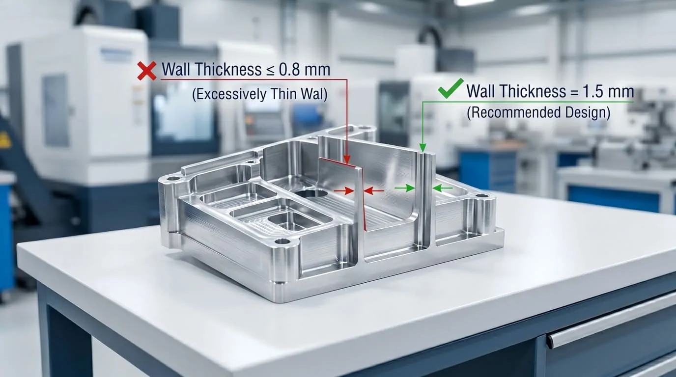
In general, recommended CNC wall thickness depends on material type and part geometry. For most metal parts such as aluminum and stainless steel, a minimum wall thickness of around 0.8 mm is commonly used in standard CNC machining applications, while engineering plastics typically require greater thickness for structural stability.
This guide explains practical CNC machining design principles, including how wall thickness interacts with DFM (Design for Manufacturability) requirements, material selection, and overall part performance. It is intended to help engineers optimize designs for both prototyping and production environments.
If you are working on full part optimization, you may also refer to our CNC Design Guide, Material Selection Guide, and DFM Guide for a more complete engineering workflow.
Wall thickness is one of the most critical factors influencing the manufacturability and performance of CNC machined parts. It directly affects structural rigidity, machining stability, dimensional accuracy, and overall production efficiency.
When wall thickness is not properly designed, it can introduce multiple manufacturing risks such as vibration during machining, tool deflection, and part deformation. These issues often result in poor surface finish, reduced dimensional accuracy, and higher scrap rates. In some cases, additional machining strategies or slower cutting parameters are required, which increases both cost and lead time.
From a manufacturing perspective, optimizing wall thickness is essential for achieving a stable and repeatable CNC process. It ensures that cutting forces are properly supported and that the part maintains its geometry throughout the machining cycle.
Wall thickness should always be considered as part of a broader DFM (Design for Manufacturability) strategy and evaluated alongside material selection and functional requirements defined in the CNC Design Guide.
Thin or inconsistent wall sections can cause vibration and instability during CNC machining, especially in parts with long unsupported features. This instability negatively affects tool performance and can lead to deviations in dimensional accuracy and surface quality.
Proper wall thickness ensures that the part maintains sufficient rigidity under both machining forces and real-world operating loads. Insufficient thickness increases the risk of deformation, particularly in load-bearing or thin-walled structural components.
Wall thickness has a direct influence on machining time, material usage, and overall production efficiency. Overly thick or conservative designs increase material waste and machining time, while excessively thin designs may require additional process control, increasing manufacturing complexity.
From a manufacturing supplier’s perspective, wall thickness is not only a design parameter but also a key factor that determines machining strategy, tooling selection, and production stability.
In practical CNC production, parts with very thin or highly variable wall thickness often require additional fixturing, reduced cutting speeds, or specialized tooling to maintain stability. These adjustments can increase setup time and reduce overall machining efficiency.
On the other hand, designs with consistent and practical wall thickness allow suppliers to use standard machining strategies, which improves repeatability, reduces production risk, and helps maintain more predictable lead times and cost structures.
In high-volume or production environments, even small improvements in wall thickness optimization can significantly reduce cumulative machining time and tooling wear across batches.
For this reason, experienced manufacturers often evaluate wall thickness not only from a structural perspective, but also from a process efficiency and scalability standpoint.
Upload your drawings or CAD files for lead time evaluation, engineering feedback, and manufacturing recommendations.
Wall thickness in CNC machining is not defined by a single fixed value. Instead, it is influenced by a combination of material properties, part geometry, machining process constraints, tolerance requirements, functional performance, and production strategy.
Understanding these factors allows engineers to determine appropriate wall thickness for specific applications, rather than relying on generic minimum values that may not reflect real manufacturing conditions.
Different materials behave differently during CNC machining due to variations in strength, stiffness, hardness, and thermal stability.
Aluminum alloys typically allow more aggressive wall thickness optimization because of their excellent machinability and rigidity. Engineering plastics, such as ABS, Nylon, and PEEK, generally require thicker walls to maintain structural stability and avoid deformation. Materials like stainless steel and titanium often require more conservative design due to higher cutting forces and reduced machinability.
The overall geometry of a part significantly affects achievable wall thickness. Thin walls combined with long spans, deep cavities, or unsupported structures are more susceptible to vibration and deformation during machining.
Complex geometries often require additional design considerations such as reinforcement ribs, reduced depth-to-width ratios, or modified internal features to ensure stable machining conditions.
CNC machining capability is directly influenced by tooling selection, tool length, cutting strategy, and fixture stability.
Deep features requiring long-reach tools increase cutting force and deflection risk, which can limit achievable wall thickness. Similarly, insufficient fixturing support can lead to instability during machining, especially in thin-walled structures or complex components.
Tighter tolerances increase machining complexity and reduce allowable design flexibility.
Thin-walled parts combined with high precision requirements often require slower machining speeds, additional setup operations, and more stringent inspection processes. In many cases, tolerance optimization is as important as geometric optimization when determining feasible wall thickness.
Wall thickness must always be evaluated in relation to the final application of the part.
Structural components, load-bearing elements, and parts exposed to mechanical stress typically require thicker walls to ensure performance reliability. In contrast, non-structural or lightweight components may allow for more optimized material usage.
Production strategy plays an important role in determining wall thickness decisions.
Prototype parts often allow more flexibility in design optimization, while high-volume production requires greater process stability and repeatability. In production environments, consistent wall thickness is often preferred to ensure predictable cycle times, tool life, and manufacturing efficiency.
From a manufacturing perspective, wall thickness is not only a design parameter but also a key factor that directly impacts machining strategy, tooling selection, and production stability.
In real CNC production environments, the final achievable wall thickness is often constrained not only by theoretical design rules, but also by tool rigidity, fixture setup, and process stability requirements. For example, long-reach tooling or insufficient workholding can require more conservative wall thickness than initially expected in the design stage.
In production scenarios, suppliers tend to prioritize repeatability and process reliability over aggressive material reduction. As a result, wall thickness optimization is often a balance between design intent and manufacturability constraints rather than a purely geometric decision.
When wall thickness is below a practical manufacturing threshold, CNC machined parts can experience a range of performance and production issues. These issues are not only related to structural weakness but also to machining stability, dimensional accuracy, and overall process reliability.
In many cases, thin-wall designs may still be theoretically feasible but become difficult or inefficient to manufacture at scale.
Thin walls have lower rigidity, making them more susceptible to vibration during CNC machining. This instability can affect cutting tool engagement and result in inconsistent surface finish or dimensional variation.
In severe cases, excessive vibration may require reduced cutting speeds or additional machining passes, increasing overall production time.
From a design perspective, vibration issues are often evaluated early in CNC Design Guide workflows to ensure manufacturability.
When walls are too thin, cutting forces can cause slight deformation of the part during machining. This leads to tool deflection and dimensional inaccuracy, especially in high-precision components.
Maintaining stable geometry becomes more difficult when thin walls are combined with tight tolerance requirements defined in the DFM (Design for Manufacturability) process.
Thin-walled components are more sensitive to internal stress release during material removal. This can result in warping, twisting, or localized deformation after machining.
This effect is more pronounced in materials with higher internal stress or lower stiffness, making Material Selection Guide an important reference when designing thin-wall parts.
Insufficient wall thickness can lead to chatter marks, tool vibration patterns, and uneven surface finish. These surface defects are often a direct result of insufficient structural support during cutting operations.
In many cases, achieving high-quality surface finish may require additional post-processing steps, which should be considered alongside Surface Finish Guide requirements.
Although reducing wall thickness may seem like a way to save material, it often leads to higher manufacturing costs due to slower machining speeds, increased setup complexity, and additional quality control requirements.
From a supplier perspective, thin-wall parts often require more conservative machining strategies to maintain stability, which directly increases production lead time.
From a manufacturing standpoint, thin-wall parts are typically more sensitive to process variation and require significantly more control during machining. In real production environments, suppliers often need to adjust tooling strategies, reduce cutting parameters, and increase inspection frequency to ensure consistent results.
As a result, even if a thin-wall design is technically achievable, it may not always be economically efficient for production. This is why experienced manufacturers evaluate both design intent and production scalability before confirming manufacturability.
Recommended wall thickness in CNC machining depends primarily on material type, part geometry, and functional requirements. While exact values can vary based on application, there are widely accepted engineering ranges that are used as practical manufacturing references.
These guidelines are not absolute limits, but rather proven industry benchmarks that help ensure machinability, structural stability, and cost efficiency.
For most CNC machined metal parts, wall thickness can generally be kept relatively thin due to higher material strength and stiffness.
Aluminum alloys (e.g., 6061, 7075): typically 0.8 mm and above
Stainless steel (e.g., 304, 316): typically 0.8–1.0 mm and above
Titanium (Grade 5): typically 1.0 mm and above, depending on geometry and machining depth
Metals allow tighter wall thickness designs, but stability must still be evaluated in relation to feature height and tool accessibility.
From a manufacturing perspective, these values are commonly used as baseline references in Material Selection Guide workflows when evaluating design feasibility.
Engineering plastics generally require thicker walls compared to metals due to lower stiffness and higher sensitivity to deformation.
ABS: typically 1.5–2.0 mm and above
Nylon: typically 1.5–2.5 mm and above
POM (Delrin): typically 1.5–2.0 mm and above
PEEK: typically 2.0 mm and above
Plastic materials are more sensitive to warping, shrinkage, and machining heat, which makes conservative wall thickness design more important for dimensional stability.
Although thin-wall machining is possible, it requires careful evaluation of machining strategy, tooling selection, and fixturing stability.
In practice, the achievable minimum wall thickness may be higher than theoretical values depending on part geometry, tolerance requirements, and production volume.
For complex or high-precision components, wall thickness should always be evaluated together with DFM (Design for Manufacturability) principles to ensure process stability.
In general, metals allow thinner wall sections due to higher rigidity, while plastics require more conservative thickness design.
Material Type | Typical Minimum Wall Thickness |
|---|---|
Aluminum | ~0.8 mm |
Stainless Steel | ~0.8–1.0 mm |
Titanium | ~1.0 mm+ |
Engineering Plastics | ~1.5–2.5 mm+ |
This comparison serves as a practical reference for early-stage design decisions, especially during material selection and concept development.
From a manufacturing perspective, these recommended values are not strict limits but practical engineering baselines derived from real production experience.
In actual CNC production, achievable wall thickness often depends on tool rigidity, fixture stability, machining depth, and part geometry rather than material specification alone. For example, even if a material theoretically allows thinner walls, production constraints such as vibration control or tool deflection may require more conservative design choices.
This is why experienced suppliers typically evaluate wall thickness together with machining strategy and production requirements rather than treating it as a standalone design parameter.
Designing thin-wall CNC parts requires balancing weight reduction, structural performance, and manufacturability. While reducing wall thickness can improve material efficiency, it must always be evaluated against machining stability and functional requirements.
The following design recommendations are widely used in industrial CNC machining to improve part performance and reduce production risks.
When thin walls are required, adding support features such as ribs or reinforcement structures can significantly improve rigidity without increasing overall material usage.
These features help distribute stress more evenly and reduce deformation during both machining and end-use conditions.
This approach is commonly evaluated in early-stage DFM (Design for Manufacturability) workflows to ensure structural feasibility.
Deep, unsupported wall structures are highly prone to vibration and deflection during CNC machining. As wall height increases relative to thickness, stability decreases significantly.
Reducing unsupported spans or introducing intermediate support geometry helps maintain machining stability and improves dimensional accuracy.
Sharp internal corners should be avoided in thin-wall designs because they increase stress concentration and are not efficiently machinable with standard CNC tooling.
Adding appropriate corner radii improves tool access, reduces machining stress, and enhances overall structural integrity.
This consideration is often defined early in the CNC Design Guide process.
Excessively deep pockets combined with thin walls can create machining instability and increase tool deflection risk.
Maintaining balanced depth-to-width ratios helps ensure smoother machining operations and reduces the need for specialized tooling or extended machining time.
Material selection plays a critical role in thin-wall performance. Metals such as aluminum are generally more suitable for thin-wall designs, while engineering plastics require more conservative wall thickness due to lower stiffness.
Early alignment with the Material Selection Guide helps avoid design revisions later in the production cycle.
From a manufacturing perspective, thin-wall optimization is not only a geometric design challenge but also a process stability consideration.
In real CNC production environments, even well-designed thin-wall parts may require adjustments based on tooling limitations, fixture rigidity, and machining strategy. Suppliers often evaluate whether a design is not only manufacturable but also stable enough for repeatable production.
As a result, thin-wall optimization is typically a collaborative process between design intent and manufacturing capability rather than a purely theoretical calculation.
In CNC design, selecting between thin-wall and thick-wall structures involves balancing weight, strength, manufacturability, and cost efficiency. Each approach has distinct advantages and limitations depending on the application and production requirements.
To simplify decision-making, the key differences are summarized below.
Design Aspect | Thin Walls | Thick Walls |
|---|---|---|
Structural Strength | Lower rigidity, more flexible | Higher rigidity, better load resistance |
Machining Stability | Prone to vibration and deflection | Stable during machining |
Dimensional Accuracy | More sensitive to deformation | More consistent and stable |
Material Usage | Lower material consumption | Higher material consumption |
Machining Complexity | Higher complexity | Easier machining process |
Tool Wear Risk | Higher due to instability | Lower due to stable cutting |
Cost Efficiency | Lower material cost but higher machining risk | Higher material cost but lower process risk |
Thin walls are generally preferred when weight reduction and compact design are priorities. However, they introduce higher machining risk and require more controlled production conditions.
Thick walls provide more stable machining performance and are typically used in structural or load-bearing applications where reliability is more important than material savings.
Thin-wall designs are commonly used in:
Lightweight housings
Space-constrained enclosures
Non-structural components
Thick-wall designs are commonly used in:
Load-bearing brackets
Structural mechanical parts
High-stress industrial components
From a manufacturing perspective, the choice between thin and thick wall designs is often driven more by process stability than by theoretical design preference.
While thin walls can reduce material usage, they frequently introduce machining instability, increased inspection requirements, and higher risk of production variation. Thick walls, although heavier, tend to offer more predictable machining performance and improved batch-to-batch consistency.
In industrial production, suppliers often prioritize stability and repeatability over aggressive material reduction, especially in medium to high-volume manufacturing.
Even experienced engineers can encounter design issues related to wall thickness that negatively affect manufacturability, machining stability, and overall production cost.
Understanding these common mistakes helps prevent redesigns, reduce production risks, and improve overall CNC part quality.
One of the most common mistakes is designing wall thickness below practical machining capabilities for a given material or geometry.
While extremely thin walls may be theoretically possible, they often introduce instability during machining and increase the risk of deformation or dimensional inaccuracy.
Different materials respond differently to CNC machining. Applying the same wall thickness logic across aluminum, stainless steel, and engineering plastics often leads to unexpected manufacturing issues.
Material properties such as stiffness, thermal expansion, and machinability should always be considered when defining wall thickness.
This is closely related to decisions made in the Material Selection Guide.
Thin walls combined with deep pockets significantly increase machining difficulty. This geometry reduces structural support during cutting operations and increases tool deflection risk.
In many cases, this combination requires process adjustments or design simplification to ensure manufacturability.
Assigning tight tolerances to thin-wall structures is a common design risk. Thin features are more susceptible to vibration and deformation during machining, making precision control more difficult.
In such cases, tolerance optimization should be evaluated together with DFM (Design for Manufacturability) principles.
Excessive focus on weight reduction can lead to overly thin structures that compromise manufacturability and structural stability.
While lightweight design is important, it should always be balanced with machining feasibility and production reliability.
Wall thickness decisions made without considering tooling, fixturing, and machining strategy often result in unexpected production challenges.
From a manufacturing perspective, design decisions should always align with real CNC machining constraints defined in the CNC Design Guide.
From a manufacturing standpoint, most wall thickness-related issues are not caused by material limitations, but by design decisions that do not account for real machining conditions.
In actual CNC production, factors such as tool rigidity, fixture stability, and machining sequence often determine whether a thin-wall design is feasible. As a result, many manufacturability issues could be avoided by considering production constraints earlier in the design phase.
Experienced suppliers typically evaluate these risks during early DFM review to prevent costly redesigns and production delays.
Wall thickness is one of the most critical factors affecting CNC manufacturability, cost, and production stability. Before moving into production, our engineering team can help evaluate your design to identify potential risks and optimize wall thickness for real manufacturing conditions.


