
- Home
- Capabilities
- Solution
- Material
- Industry
- Resources
- Request a Quote
Views: 0 Author: Site Editor Publish Time: 2026-06-22 Origin: Site
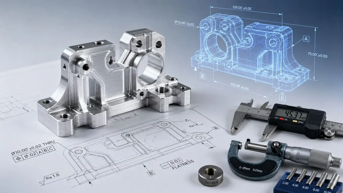
Tolerances are one of the biggest cost drivers in CNC machining. A tighter tolerance can improve fit, alignment, sealing, or motion control, but it can also require slower machining, more precise fixturing, additional finishing passes, stricter inspection, and higher scrap risk. For this reason, the most cost-effective CNC parts are not always the parts with the tightest tolerances — they are the parts with the right tolerances in the right places.
In many CNC projects, only a few features truly require precision control. Bearing seats, dowel pin holes, sealing surfaces, shaft diameters, and critical mating faces may need tighter tolerances. However, cosmetic profiles, clearance cutouts, non-functional pockets, and general outer dimensions can often use standard machining tolerances without affecting part performance.
This guide explains how to specify CNC machining tolerances clearly and practically. You will learn what standard CNC tolerances mean, why tight tolerances increase cost, how to avoid over-tolerancing, which features require tighter control, and how material, wall thickness, hole design, internal corner radius, threads, GD&T, and machining process selection affect tolerance capability.
From a supplier perspective, a good tolerance drawing does more than define accuracy. It tells the machining team which features are function-critical and which features have more flexibility. This helps reduce unnecessary cost while keeping the final part reliable for assembly and use.
If you need support reviewing tolerance requirements before production, NAITE TECH provides custom CNC machining services with engineering support for CAD review, 2D drawing review, DFM feedback, and practical tolerance optimization.
This guide covers practical CNC machining tolerance principles, helping engineers specify accurate, manufacturable, and cost-effective tolerances without adding unnecessary machining or inspection cost.
Understand what CNC machining tolerances mean, how they are shown on engineering drawings, and why they affect fit, function, inspection, and manufacturing cost.
Learn what tolerance ranges are commonly considered practical for non-critical dimensions, milled features, holes, shafts, and general machined parts.
Explore how tighter tolerances can increase machining time, setup complexity, finishing passes, inspection requirements, scrap risk, and total production cost.
Identify common over-tolerancing problems, such as applying tight tolerances to cosmetic surfaces, clearance features, non-functional pockets, or every drawing dimension.
Learn how to decide which features require tighter tolerance control, including bearing seats, dowel pin holes, sealing surfaces, shaft diameters, and mating interfaces.
Understand how hole function, pocket depth, slot width, tool access, internal radius, and milling strategy affect tolerance capability and machining consistency.
See how aluminum, stainless steel, titanium, plastics, wall thickness, thin features, and material stress influence dimensional stability after machining.
Learn when GD&T can improve tolerance clarity for hole patterns, mating surfaces, datums, flatness, parallelism, and rotating components.
Learn how to apply tight tolerances only where they are functionally required, use standard tolerances elsewhere, and reduce unnecessary machining cost.
CNC machining tolerances define the acceptable amount of dimensional variation allowed on a machined part. In a technical drawing, a tolerance tells the manufacturer how much a feature can deviate from its nominal dimension while still meeting the design requirement.
For example, if a hole is specified as:
Ø10.00 ±0.05 mm
the finished hole diameter can range from 9.95 mm to 10.05 mm and still be considered acceptable.
Tolerances are necessary because no machining process can produce every feature at the exact nominal dimension. Cutting tools wear over time, materials behave differently during machining, fixtures introduce small variations, and inspection methods also have measurement limits. A well-designed tolerance defines what level of variation is acceptable without making the part more difficult or expensive to manufacture than necessary.
In CNC machining, tolerances are commonly applied to:
Hole diameters
Shaft diameters
Slot widths
Pocket depths
Surface flatness
Hole positions
Threaded features
Mating surfaces
Overall length, width, and height
Critical assembly interfaces
However, not every feature needs the same level of precision. A bearing seat may require a tight diameter tolerance, while a cosmetic outer profile, clearance cutout, or non-functional pocket may only need a standard general tolerance. The key is to match the tolerance to the function of the feature.
For broader CNC part design rules beyond tolerances, you can also review NAITE TECH’s CNC design for manufacturability guidelines.
Most CNC drawings use a combination of general tolerances and feature-specific tolerances.
General tolerances apply to dimensions that do not have an individually specified tolerance. These are often shown in the title block of a technical drawing and are typically used for non-critical features such as external profiles, basic pocket shapes, clearance areas, and cosmetic surfaces.
Feature-specific tolerances are applied directly to important dimensions that affect part function. These may include bearing bores, dowel pin holes, sealing surfaces, shaft diameters, precision slots, or datum-related hole patterns.
A practical CNC tolerance strategy usually separates critical features from non-critical geometry:
Feature Type | Recommended Tolerance Approach | Why It Matters |
|---|---|---|
Non-critical external dimensions | Use general tolerances | Keeps machining and inspection cost lower |
Clearance holes | Use standard or moderate tolerance | Usually only need enough space for fasteners |
Dowel pin holes | Use tighter diameter and position control | Affects alignment and assembly accuracy |
Bearing seats | Use tight diameter tolerance | Affects fit, rotation, and performance |
Sealing surfaces | Control flatness or surface finish if needed | Affects leakage and sealing reliability |
Cosmetic surfaces | Avoid unnecessary tight tolerances | Does not usually improve part function |
A common mistake is applying the same tight tolerance to every dimension on a drawing. This increases machining time, inspection effort, and cost, even when many features do not require high precision.
In real CNC machining projects, a clear tolerance hierarchy is often more valuable than simply making every dimension tight. When a drawing clearly identifies critical features, datum references, and functional surfaces, the machining team can focus precision where it matters most.
Before quoting a CNC project, NAITE TECH engineers often review whether the specified tolerances are functionally necessary or whether some dimensions can remain under standard machining tolerances without affecting assembly or performance. This helps reduce unnecessary setup complexity, avoid over-inspection, and keep the final part cost under control.
Standard CNC machining tolerances are general tolerance ranges that can usually be achieved without requiring special process control, advanced inspection, or additional finishing operations. These tolerances are commonly used for non-critical dimensions, general profiles, clearance areas, and features that do not directly affect assembly, sealing, motion, or alignment.
For many CNC machined parts, a practical general tolerance may fall around ±0.10 mm to ±0.05 mm, depending on the material, part size, geometry, feature depth, machining process, and inspection requirements. Tighter tolerances may be possible, but they should be specified only when the feature requires additional precision for function.
It is important to understand that there is no single “standard CNC tolerance” that applies to every part. A small aluminum bracket, a stainless steel shaft, a thin-wall housing, a deep pocket, and a plastic machined component may all require different tolerance expectations. The same tolerance value can be easy to achieve on one feature and difficult or costly on another.
A better approach is to define tolerances based on feature function and manufacturing risk.
Feature Type | Practical Tolerance Approach | Cost Impact |
|---|---|---|
Non-critical external profiles | Use general drawing tolerances | Low |
Basic milled surfaces | Standard machining tolerance is usually acceptable | Low to medium |
Clearance holes | Moderate tolerance is usually sufficient | Low |
Dowel pin holes | Use tighter diameter and position control | Medium |
Bearing seats | Specify tight diameter tolerance based on fit requirement | Medium to high |
Shaft diameters | Use appropriate fit tolerance for rotation or assembly | Medium |
Deep pockets or slots | Tolerance depends on tool access and depth | Medium to high |
Large flat surfaces | Flatness depends on material, size, and setup | Medium to high |
Thin-wall features | Higher risk of deflection and deformation | High |
Cosmetic surfaces | Avoid unnecessary tight tolerances | Low if not over-specified |
When specifying standard tolerances, engineers should avoid using the tightest possible value by default. A tolerance should be tight enough to ensure the part works, but not so tight that it increases machining cost without improving performance.
For example, a clearance hole for a screw usually does not need the same tolerance as a dowel pin hole used for precision alignment. A cosmetic outer edge usually does not need the same tolerance as a bearing seat. A non-functional pocket usually does not need the same depth tolerance as a sealing surface.
If your project involves multiple manufacturing processes or you want to compare tolerance expectations across different methods, you can also refer to NAITE TECH’s manufacturing tolerance reference resources.
Standard tolerances are usually the most cost-effective starting point for CNC machined parts because they allow the manufacturer to use efficient machining strategies, standard tooling, practical setup methods, and normal inspection procedures.
Using standard tolerances where possible can help reduce:
Machining time
Setup complexity
Tooling risk
Inspection time
Rework
Scrap rate
Overall part cost
This does not mean that tight tolerances should be avoided completely. Many CNC parts need tight tolerances for critical features. The goal is to apply tight tolerances selectively, only where they affect the part’s function.
A good CNC tolerance strategy usually includes:
General tolerances for non-critical dimensions
Feature-specific tolerances for functional areas
Clear datum references for inspection
Standard fits for holes, pins, shafts, and bearings
Practical tolerance values based on material and geometry
Supplier review before production
For broader part design rules, tolerance decisions should also be considered together with geometry, material, tool access, and feature function. NAITE TECH’s CNC part design best practices provide a useful foundation for designing more manufacturable CNC components.
From a machining supplier’s perspective, standard tolerances help keep the manufacturing process stable and predictable. When non-critical features are allowed to use practical general tolerances, the machining team can focus more attention on the features that truly affect fit, alignment, sealing, or mechanical performance.
In many CNC projects, the most effective cost-saving opportunity is not changing the part design completely. It is adjusting the tolerance strategy so that precision is applied only where it creates functional value.
Tight tolerances increase CNC machining cost because they require more control at every stage of production. The cost is not only related to cutting the material. It also comes from setup planning, fixture stability, machining strategy, tool condition, inspection time, and the risk of producing parts outside the required tolerance range.
A tolerance such as ±0.10 mm may be practical for many general CNC features, while ±0.01 mm or tighter may require a much more controlled process. The tighter the tolerance, the smaller the acceptable variation. This means the machining process has less room for tool wear, thermal movement, material stress, fixture variation, or measurement uncertainty.
In many cases, tight tolerances can be achieved, but they should be applied only to features that truly require them for part function.
CNC machining accuracy depends heavily on how the part is held during production. For loose or standard tolerances, a practical fixture may be enough. For tight tolerances, the setup often needs to be more rigid, repeatable, and carefully aligned.
Tight tolerance features may require:
More accurate datum positioning
Custom fixtures
Additional setup verification
Reduced clamping distortion
More controlled part orientation
Better repeatability between operations
If a part needs to be machined from multiple sides, each setup introduces a small amount of variation. This is especially important when tight tolerances control the relationship between features on different faces of the part.
For complex parts with critical features across multiple angles or surfaces, 5-axis CNC machining for complex precision parts can sometimes reduce setup-related tolerance errors by allowing more features to be machined in fewer operations.
Standard tolerance features can often be machined efficiently with normal roughing and finishing strategies. Tight tolerance features may require slower cutting parameters, lighter finishing cuts, and additional passes to improve dimensional accuracy and surface consistency.
This can increase cost because the machine spends more time on each part.
For example, a pocket with a standard depth tolerance may only need a normal finishing pass. A precision pocket depth, tight slot width, or critical mating surface may require extra stock control, spring passes, or additional measurement between operations.
Tighter tolerances may also limit how aggressively the part can be machined. Cutting too fast can create heat, tool deflection, vibration, or surface variation, all of which can affect dimensional accuracy.
Cutting tools do not stay perfectly sharp throughout production. As a tool wears, feature dimensions can gradually shift. For standard tolerances, this small dimensional change may still be acceptable. For tight tolerances, tool wear must be monitored more carefully.
Tool deflection is another major factor. Long, small-diameter, or unsupported tools can bend slightly during cutting. This is common when machining deep pockets, narrow slots, small internal radii, and hard-to-access features.
When tight tolerances are applied to these difficult features, the machining process may require:
Shorter tools where possible
More rigid tool holders
Reduced cutting forces
Additional finishing passes
More frequent tool replacement
More careful inspection during production
For milled pockets, slots, profiles, and flat surfaces, NAITE TECH provides precision CNC milling for tight-tolerance features with process planning based on part geometry and tolerance requirements.
Tight tolerances usually require more inspection. A simple caliper check may be enough for some general dimensions, but tight tolerance features may require micrometers, bore gauges, height gauges, CMM inspection, surface plates, pin gauges, thread gauges, or other controlled measurement methods.
Inspection cost increases when:
More dimensions require measurement
Measurement tools must be more precise
CMM programming is required
Each part needs detailed inspection
First article inspection is required
Inspection reports are requested
Parts must be measured in a controlled environment
This is one reason why applying tight tolerances to every dimension can increase cost even if the machining itself is not especially difficult. The inspection burden becomes much heavier.
The tighter the tolerance, the smaller the acceptable process window. A feature that is only slightly oversized, undersized, warped, or misaligned may become nonconforming.
This increases the risk of:
Re-machining
Re-inspection
Scrap
Delayed delivery
Higher production cost
More conservative machining strategies
For prototype parts, this may mean extra machining time. For production parts, it may affect yield and repeatability across the entire batch.
Some tolerances become expensive not because the number is extremely tight, but because the material or geometry is difficult to control.
For example:
Thin aluminum parts may warp after material removal.
Stainless steel may require slower machining and more careful heat control.
Titanium can be difficult to cut and may increase tool wear.
Plastics may move because of temperature, moisture, or internal stress.
Large flat surfaces may require careful stress control and inspection.
Deep pockets may be affected by tool deflection.
This means a tolerance that is practical on a small rigid block may be difficult on a thin-wall housing or a large lightweight plate.
In CNC machining, suppliers do not only quote the shape of the part. They also quote the risk of holding the required tolerances repeatedly. A tight tolerance on a short, rigid diameter may be manageable, while the same tolerance on a thin wall, deep pocket, or large flat surface may require a more controlled and expensive process.
This is why tolerance review is an important part of DFM. Before production, NAITE TECH can help evaluate which tolerance requirements are critical, which features create manufacturing risk, and where standard tolerances may be used to reduce cost without affecting function.
For projects where tolerance requirements are unclear or cost-sensitive, NAITE TECH’s CNC machining tolerance review can help identify practical ways to improve manufacturability before machining begins.
Over-tolerancing is one of the most common reasons CNC machined parts become more expensive than necessary. It happens when tolerances are specified tighter than the part actually needs for fit, function, assembly, sealing, or performance.
In many cases, over-tolerancing does not improve the final part. Instead, it increases machining time, inspection effort, setup complexity, and production risk.
For example, a drawing may specify ±0.01 mm for all dimensions, even though only a few features affect assembly. The bearing seat, dowel pin holes, or sealing surface may need tight control, but cosmetic edges, clearance cutouts, and non-functional pockets usually do not. When every feature is treated as critical, the entire part becomes more difficult and expensive to manufacture.
Over-tolerancing means applying stricter tolerance requirements than the design actually requires. This can happen at the drawing level, feature level, or title block level.
Common examples include:
Applying tight tolerances to every dimension
Using a very strict general tolerance in the drawing title block
Specifying tight tolerances on cosmetic surfaces
Applying precision tolerances to clearance holes
Requiring tight flatness on large non-mating surfaces
Adding GD&T controls without functional purpose
Using tight position tolerances on features that do not affect assembly
Specifying unnecessary tight tolerances on deep pockets or thin walls
A tolerance should always answer a functional question:
What happens if this feature is slightly larger, smaller, flatter, deeper, or shifted within a reasonable range?
If the answer is “the part still works,” then a tight tolerance may not be necessary.
Over-tolerancing often happens because designers want to avoid risk. When a part is important, it may feel safer to make every dimension tight. However, in CNC machining, this approach can create the opposite result. It can make the part harder to produce, harder to inspect, and more expensive to repeat consistently.
Common causes of over-tolerancing include:
Copying tolerances from an old drawing
Using default CAD or drawing templates
Applying one tight tolerance to the entire title block
Not separating functional and non-functional features
Trying to compensate for unclear assembly requirements
Lack of supplier feedback during the design stage
Misunderstanding what tolerance level the part actually needs
For example, an engineer may specify a tight tolerance on a pocket depth because it appears important in the CAD model. But if that pocket only provides clearance or weight reduction, the tight tolerance may not add functional value.
Over-tolerancing increases cost because it forces the manufacturer to treat more features as precision-critical. This affects machining, inspection, and quality control.
When too many dimensions are tightly controlled, the supplier may need to:
Use slower machining strategies
Add more finishing passes
Create more complex fixtures
Inspect more dimensions
Use more advanced measuring equipment
Control tool wear more frequently
Reduce production speed
Allow for more scrap or rework risk
Even if the part looks simple, excessive tolerance requirements can make the manufacturing process significantly more demanding.
A simple bracket with standard tolerances may be easy to machine. The same bracket with tight tolerances on every surface, hole, slot, and edge may require a much more controlled process and longer inspection time.
A practical way to avoid over-tolerancing is to separate critical features from non-critical geometry.
Feature | Poor Tolerance Strategy | Better Tolerance Strategy |
|---|---|---|
General outer profile | ±0.01 mm | Use standard general tolerance |
Clearance screw holes | ±0.01 mm | Use practical clearance tolerance |
Dowel pin holes | Same as all other holes | Use precision diameter and position tolerance |
Bearing seat | Same as all other diameters | Apply fit-based tight tolerance |
Cosmetic chamfers | Tight dimensional tolerance | Use standard edge break requirement |
Non-functional pockets | Tight depth and width tolerance | Use general tolerance unless function-critical |
Sealing surface | Not clearly identified | Specify flatness or finish only where needed |
This approach keeps the important features accurate while avoiding unnecessary cost on dimensions that do not affect the part’s performance.
The best way to avoid over-tolerancing is to define the function of each important feature before assigning a tolerance.
Before applying a tight tolerance, ask:
Does this feature affect assembly?
Does it locate another part?
Does it control movement, rotation, or sliding?
Does it affect sealing or leakage?
Does it act as a datum?
Does it support a bearing, shaft, pin, or fastener?
Does it require inspection documentation?
Would the part still function with a looser tolerance?
If the feature does not affect function, it can often use a standard tolerance.
A good CNC drawing should make it easy for the supplier to understand which features are critical. It should not force the machining team to guess which dimensions matter most.
For broader manufacturability rules, review NAITE TECH’s CNC part design best practices to understand how tolerance, geometry, material, and tool access work together in CNC part design.
During drawing review, one of the most common cost drivers NAITE TECH sees is applying tight tolerances to every dimension. In many projects, only a small number of features truly affect assembly, alignment, sealing, or mechanical performance.
A better approach is to define critical features clearly and allow standard tolerances for the rest of the part. This helps the machining team focus process control where it creates real value, while avoiding unnecessary machining time and inspection cost on non-critical geometry.
For cost-sensitive parts, NAITE TECH can review drawings and provide precision CNC machining support to help identify tolerance requirements that may increase cost without improving part function.
Not every dimension on a CNC machined part needs a tight tolerance. The best tolerance strategy is based on function. Before applying a tight tolerance, engineers should identify which features affect assembly, alignment, sealing, movement, load transfer, or inspection.
A good rule is simple:
If a feature directly affects how the part fits, moves, seals, aligns, or performs, it may need tighter tolerance control. If it does not affect function, a standard tolerance is usually more cost-effective.
This function-based approach helps prevent over-tolerancing while keeping critical features accurate.
Some CNC features are directly related to part performance and may require tighter tolerance control. These features should be reviewed carefully during design and manufacturing planning.
Common examples include:
Bearing seats
Dowel pin holes
Press-fit holes
Slip-fit holes
Shaft diameters
Sealing surfaces
Mating surfaces
Precision hole patterns
Datum surfaces
Sliding or rotating interfaces
Optical, medical, aerospace, or robotic interfaces
Features that control assembly stack-up
For these features, the tolerance should be chosen based on functional requirements, not by using a default value. For example, a bearing bore should be toleranced according to the required bearing fit, while a dowel pin hole should be controlled for both diameter and position.
Many CNC features are important for shape, clearance, or appearance but do not require precision-level control. Applying tight tolerances to these features often increases cost without improving performance.
Examples include:
Cosmetic outer profiles
Non-functional pockets
Weight-reduction cutouts
General clearance areas
Basic chamfers
Edge breaks
Decorative surfaces
Large non-mating surfaces
Screw clearance holes
Internal cavities used only for material removal
These features can often use general drawing tolerances. If the feature does not locate another component, support a fit, create a seal, or control movement, it usually does not need a tight tolerance.
Before specifying a tight tolerance on a CNC drawing, ask the following questions:
Question | Why It Matters |
|---|---|
Does this feature affect assembly? | Assembly features often need controlled size or position |
Does it locate another component? | Locating features may require tighter position tolerance |
Does it support a bearing, shaft, or pin? | Fit-based features usually need precise diameter control |
Does it affect sealing? | Sealing surfaces may need flatness or surface finish control |
Does it control sliding or rotation? | Moving interfaces need controlled clearance |
Is this feature used as a datum? | Datum features affect inspection and feature relationships |
Does it require inspection documentation? | More inspection may increase cost |
Would the part still work with a looser tolerance? | If yes, a tight tolerance may not be necessary |
This checklist helps engineers decide where precision is truly needed and where standard tolerances are more practical.
The same type of feature may require different tolerances depending on its function.
For example, not all holes should be treated the same:
A screw clearance hole may only need enough space for the fastener.
A dowel pin hole may need tight diameter and position control.
A bearing hole may need a fit-based tolerance.
A threaded hole may need proper thread depth and engagement.
A sealing hole may require both dimensional and surface requirements.
For more detailed hole design rules, review NAITE TECH’s CNC hole design recommendations.
The same logic applies to milled surfaces. A cosmetic face, a mounting face, and a sealing face may all look similar in CAD, but they do not require the same tolerance strategy. The tolerance should reflect the functional purpose of the surface.
Tolerance decisions should also consider how multiple parts fit together in an assembly. Even if each individual part is within tolerance, small variations can accumulate across several components. This is called tolerance stack-up.
Tolerance stack-up is especially important for:
Multi-part assemblies
Housings and covers
Dowel-located assemblies
Sliding mechanisms
Gear or bearing alignment
Optical or sensor positioning
Robotic and automation components
If a feature controls the position of another part in an assembly, it may need tighter tolerance or clearer GD&T control. If the feature is only cosmetic or provides extra clearance, it can usually remain under standard tolerance.
A common mistake is using tight tolerances to compensate for unclear design requirements. If the designer is unsure which features are critical, it may feel safer to make everything tight. However, this often increases cost and makes the drawing harder to manufacture.
Instead, the drawing should clearly define:
Which features are critical
Which surfaces act as datums
Which holes are for alignment
Which features are for clearance
Which dimensions affect fit or motion
Which tolerances are required for inspection
For general tolerance planning and manufacturable CNC geometry, NAITE TECH’s DFM principles for CNC machined parts can help connect feature function, material choice, and machining process limitations.
A good tolerance drawing tells the supplier what matters most. When critical features are clearly identified, the machining team can plan fixtures, toolpaths, inspection methods, and process controls around those features.
In NAITE TECH’s engineering review process, tolerance questions are often evaluated by function first. If a dimension affects fit, sealing, alignment, or movement, it receives closer attention. If a feature does not affect part performance, standard machining tolerance is often the more practical and cost-effective choice.
Hole tolerances are among the most important tolerance decisions in CNC machined parts. Holes may be used for clearance, alignment, fastening, bearing support, press fits, fluid flow, or sealing. Because each hole type has a different function, not all holes should use the same tolerance.
A common mistake is applying one tight tolerance to every hole on the drawing. This may increase machining and inspection cost without improving assembly performance. A better approach is to define the purpose of each hole first, then apply the appropriate tolerance based on function.
Clearance holes are used to allow screws, bolts, pins, or other fasteners to pass through a part. In most cases, the fastener does not need a precision fit inside the clearance hole. The hole simply needs enough space for assembly.
For this reason, clearance holes usually do not require tight diameter tolerances. Standard or moderately controlled tolerances are often sufficient.
Clearance hole tolerance depends on:
Fastener size
Assembly clearance requirement
Positional relationship to mating parts
Whether the hole is used for adjustment
Whether the fastener head, washer, or counterbore must seat properly
If the hole only provides clearance for a screw, applying a very tight diameter tolerance may not add functional value. However, if the clearance hole position affects alignment between parts, the hole position may need more control than the hole diameter.
For more detailed hole geometry, depth, and manufacturability recommendations, review NAITE TECH’s DFM guidelines for CNC holes.
Dowel pin holes are used for accurate alignment between parts. Unlike clearance holes, dowel holes often require tighter diameter and position control because they directly affect assembly accuracy.
A dowel pin hole may need:
Precise hole diameter
Controlled hole position
Proper hole depth
Reaming or boring
Clear datum references
Fit selection based on assembly function
For example, a dowel pin used for repeatable alignment may require a controlled slip fit or press fit. In this case, both the hole size and hole location matter. If the diameter is too loose, the assembly may lose alignment. If the position is not controlled, the mating parts may not fit correctly.
When using dowel pin holes, it is usually better to specify the required fit and datum relationship rather than applying a random tight tolerance.
Press-fit and slip-fit holes require careful tolerance selection because they control how two parts assemble.
A press-fit hole is designed so that the inserted component is slightly larger than the hole, creating an interference fit. This can provide strong retention but requires controlled diameter and material consideration.
A slip-fit hole allows a pin, shaft, or component to slide into place with controlled clearance. This is useful when parts need to be assembled and disassembled or when accurate positioning is needed without force.
Fit-based holes may require tighter tolerances than general holes because small dimensional changes can affect assembly feel, retention force, or alignment accuracy.
Important design factors include:
Pin or shaft diameter
Material hardness
Required assembly force
Thermal expansion
Surface finish
Hole depth
Wall thickness around the hole
Whether the part will be assembled repeatedly
Press-fit holes in softer materials may behave differently from press-fit holes in steel. Thin walls around a press-fit hole can also deform during assembly, so geometry should be reviewed before assigning a tight tolerance.
Bearing seats and bushing bores are usually function-critical features. These holes often require controlled diameter, roundness, surface finish, and sometimes concentricity or runout depending on the application.
A bearing bore that is too tight may damage the bearing or make assembly difficult. A bore that is too loose may reduce support, alignment, or rotation performance.
When specifying bearing or bushing holes, engineers should consider:
Bearing manufacturer fit recommendations
Load direction
Rotation requirement
Housing material
Operating temperature
Assembly method
Surface finish
Inspection method
Bearing seats should not be toleranced the same way as general holes. They require fit-based tolerance decisions.
Threaded holes are different from plain holes because the function depends on thread form, pitch, engagement length, and fastener compatibility. In most cases, standard thread specifications should be used instead of custom tolerance values.
Threaded hole design should consider:
Thread size and pitch
Thread class or standard
Minimum thread engagement
Blind hole depth
Bottom clearance
Material strength
Fastener load
Tapping vs. thread milling
Inspection with thread gauges
Custom thread tolerances should only be used when there is a clear functional reason, such as sealing, high load, precision adjustment, or special assembly conditions.
For deeper guidance on threaded features, fastener clearance, and thread engagement, see NAITE TECH’s CNC thread and fastener design practices.
For many assemblies, hole position is more important than hole diameter. A clearance hole may have a loose diameter tolerance, but its position may still need to be controlled if it must align with another component.
This is especially true for:
Bolt patterns
Dowel pin patterns
Mounting plates
Housings
Enclosures
Brackets
Precision assemblies
If several holes must align with mating parts, consider using GD&T position tolerance instead of only applying ± tolerances to individual dimensions. Position tolerance can define the acceptable location of a hole pattern more clearly relative to datum features.
Deep holes are harder to control than shallow holes. As hole depth increases, the risk of tool deflection, drill walking, chip evacuation problems, heat buildup, and diameter variation also increases.
Tight tolerances on deep holes may require:
Peck drilling
Boring
Reaming
Special tooling
More inspection
Slower machining
Better chip evacuation
Additional process planning
If a deep hole does not require precision, avoid applying unnecessary tight tolerances. If the hole is function-critical, discuss feasibility with the machining supplier before finalizing the drawing.
A hole should not be toleranced only by diameter. Its function matters. A clearance hole, dowel pin hole, threaded hole, bearing hole, and sealing hole may all require different machining methods, inspection methods, and tolerance levels.
In NAITE TECH’s tolerance review process, hole features are evaluated based on their role in the assembly. If the hole controls alignment, press fit, bearing support, or sealing, it may need tighter control. If it only provides clearance, a standard tolerance is often more practical and cost-effective.
CNC milling tolerances depend on more than the machine’s accuracy. They are also affected by feature depth, cutter diameter, tool length, material behavior, workholding stability, surface access, and the number of setups required to machine the part.
Milled features such as pockets, slots, profiles, shoulders, bosses, and flat surfaces are common in CNC machined parts. Some of these features may require tight tolerance control, while others can usually follow standard machining tolerances. The key is to understand which milled features are function-critical and which are only used for clearance, weight reduction, or appearance.
NAITE TECH provides precision CNC milling for tight-tolerance features, including pockets, slots, profiles, mounting surfaces, and precision-machined components that require careful process planning.
Pockets are widely used in CNC machined housings, brackets, enclosures, and mechanical components. Pocket tolerances may apply to width, length, depth, corner radius, floor flatness, or wall position.
A pocket may require tight tolerance if it:
Holds another component
Controls assembly position
Supports a sealing surface
Locates an insert, sensor, or electronic module
Affects sliding or clearance
Defines a critical wall thickness
However, if a pocket is only used for weight reduction or material removal, a standard tolerance is often sufficient.
Pocket tolerance becomes more difficult when the pocket is deep, narrow, or requires small internal corner radii. Long tools may deflect during cutting, and small tools may require slower feeds and multiple passes. This increases machining time and tolerance risk.
Slots are commonly used for alignment, adjustment, sliding mechanisms, mounting features, and clearance. Like holes, slot tolerances should be based on function.
A slot may need tighter control when it:
Guides a sliding component
Locates another part
Controls adjustment range
Maintains alignment between assemblies
Works with a pin, key, or fastener
Affects mechanical motion
For simple clearance slots, tight width or position tolerances are often unnecessary. But for guide slots, keyways, or sliding interfaces, slot width, straightness, surface finish, and position may all affect performance.
When designing slots, engineers should consider tool access, cutter diameter, corner radius, and whether the slot can be machined with a rigid tool setup.
Profile tolerances control the shape or outline of a machined feature. They may apply to outer profiles, curved surfaces, bosses, ribs, or complex contours.
For non-critical outer profiles, standard tolerances are often acceptable. For mating profiles, sealing paths, aerodynamic surfaces, medical components, or precision assemblies, tighter profile control may be required.
Profile tolerance can become more difficult when:
The geometry is complex
The surface requires multiple toolpaths
The part needs multiple setups
Thin walls are involved
The material is difficult to machine
The contour includes small radii or deep features
For complex geometry, it is important to define which surfaces are function-critical. Not every contour on a part needs the same tolerance.
Flat surfaces may be used for mounting, sealing, locating, supporting, or cosmetic purposes. The tolerance requirement depends heavily on the function of the surface.
A mounting face may require controlled flatness or parallelism. A sealing surface may also require surface finish control. A cosmetic face, however, may only need standard dimensional tolerance and visual finishing.
Flatness becomes more difficult to control on:
Large plates
Thin-wall housings
Parts with heavy material removal
Materials with internal stress
Parts machined from multiple sides
Components with uneven wall thickness
Tight flatness requirements can significantly increase cost because they may require careful roughing, stress relief, finish machining, controlled clamping, and additional inspection.
Before specifying tight flatness, ask whether the surface truly affects sealing, assembly, alignment, or performance.
CNC milling uses rotating cutting tools, and the tool must physically access the feature being machined. Tool diameter and length strongly affect tolerance capability.
Small tools are useful for small details and tight internal radii, but they are less rigid and may require slower machining. Long tools can reach deep features, but they are more likely to deflect. Both situations can make tight tolerances harder to hold.
Tolerance risk increases when a feature requires:
Long-reach tooling
Small-diameter cutters
Deep pocket machining
Narrow slot machining
Small internal corner radii
Multiple tool changes
Restricted tool access
For this reason, tolerance decisions should be reviewed together with feature geometry. A tolerance that is practical on an open, shallow feature may become expensive on a deep, narrow feature with limited tool access.
Internal corner radius has a direct effect on CNC milling tolerance and cost. Since milling tools are round, they cannot create perfectly sharp internal corners. Smaller internal radii require smaller tools, and smaller tools are more flexible, slower, and more sensitive to deflection.
If a pocket or slot has a very small internal radius, the machining process may require:
Smaller cutters
Slower feed rates
Additional finishing passes
Longer machining time
Higher tool wear risk
More careful inspection
Whenever possible, larger internal radii improve tool access, reduce machining time, and make tolerance control more stable.
For practical radius recommendations, see NAITE TECH’s CNC internal corner radius guidelines.
Thin walls can make CNC milling tolerances harder to maintain. During machining, thin sections may flex under cutting force. After unclamping, the part may move slightly due to internal stress release. This can affect wall thickness, flatness, parallelism, and feature position.
Tight tolerances on thin-wall features often require:
Reduced cutting forces
Balanced material removal
More careful fixturing
Additional finishing passes
Controlled machining sequence
Inspection after stress release
Possible design adjustments
If a tight tolerance is applied to a thin wall without considering rigidity, the part may be difficult to machine consistently.
For more guidance on lightweight and thin-wall part design, review NAITE TECH’s thin-wall CNC machining guidelines.
For CNC milled parts, tolerance control is often limited by geometry rather than machine capability alone. A shallow open pocket may be easy to hold within a practical tolerance, while a deep narrow pocket with small corner radii may require slower machining, smaller tools, and additional process control.
During milling process review, NAITE TECH engineers evaluate tool access, pocket depth, wall thickness, internal radii, and setup strategy before confirming tight tolerance requirements. This helps identify which features are practical to control and which tolerances may increase cost without improving part function.
Wall thickness has a major impact on CNC tolerance stability. Even if a machine is capable of producing accurate dimensions, a thin-wall part may still deform during machining, after unclamping, or during inspection. This means the final measured tolerance depends not only on toolpath accuracy, but also on part rigidity and material behavior.
Thin walls are common in lightweight housings, enclosures, brackets, aerospace parts, robotic components, medical devices, and electronic assemblies. These parts often need tight tolerance control, but thin geometry can make that control more difficult and more expensive.
For this reason, wall thickness should be reviewed before applying tight tolerances to thin features.
Thin walls are less rigid than thick sections. During cutting, tool pressure can cause the wall to flex slightly. The wall may move away from the cutter and then spring back after the tool passes. This can create dimensional variation, taper, chatter marks, or inconsistent wall thickness.
Thin-wall tolerance problems can come from:
Cutting force deflection
Clamping pressure
Material stress release
Heat buildup
Tool vibration
Uneven material removal
Long unsupported wall height
Insufficient corner radius or rib support
Measurement pressure during inspection
A tolerance that is easy to achieve on a solid block may become much harder on a thin-wall housing. The geometry changes the manufacturing risk.
CNC machining removes material from a stock block or billet. When large amounts of material are removed, internal material stress can be released. This may cause the part to warp, bend, twist, or move slightly after machining.
This is especially important for:
Large aluminum plates
Thin-wall housings
Parts with deep pockets
Components with uneven wall thickness
Plastic machined parts
Stainless steel or titanium parts with high cutting forces
If a drawing specifies tight flatness, parallelism, or wall thickness tolerance on a part that may deform after machining, the manufacturer may need a more controlled process. This can include rough machining, stress relief, rest time, re-fixturing, finish machining, and additional inspection.
A practical wall thickness strategy helps improve machining stability and reduce tolerance risk. Instead of applying very tight tolerances to thin, flexible features, engineers should first improve part rigidity where possible.
Useful design strategies include:
Avoid extremely thin unsupported walls
Keep wall thickness as uniform as possible
Add ribs or support features where function allows
Avoid deep pockets with very thin remaining walls
Use larger internal radii to improve tool access
Avoid aggressive material removal from only one side
Define which thin-wall features are truly critical
Allow standard tolerances for non-functional thin sections
Discuss tight wall thickness tolerances with the machining supplier early
For more detailed lightweight part design guidance, review NAITE TECH’s CNC wall thickness design considerations.
Thin-wall geometry can also affect flatness and parallelism. A thin plate, cover, or housing may move after being released from the fixture, especially if material was removed unevenly from one side.
Tight flatness or parallelism requirements may be necessary for:
Sealing surfaces
Mounting faces
Bearing support surfaces
Optical alignment surfaces
Precision assembly interfaces
Datum surfaces used for inspection
However, tight flatness on a large thin surface can be expensive if the surface is not function-critical. Before specifying flatness, engineers should confirm whether the surface truly affects assembly, sealing, or performance.
If the surface is cosmetic or non-mating, a standard tolerance may be more practical.
Thin walls around holes can create additional tolerance challenges. A hole placed too close to a thin wall may distort during machining or assembly. Press-fit holes are especially sensitive because the inserted component applies force to the surrounding material.
Thin walls around holes may affect:
Hole roundness
Hole diameter
Press-fit strength
Thread strength
Bearing support
Sealing performance
Assembly repeatability
If a hole requires a tight tolerance, the surrounding wall thickness should be strong enough to support the required fit. Otherwise, the hole may be machined accurately but deform during assembly.
This is especially important for dowel pin holes, bearing seats, threaded holes, and press-fit features.
Different materials behave differently when machined into thin-wall geometry.
Aluminum is generally easier to machine and is often used for lightweight precision parts, but thin aluminum walls can still deflect or warp after heavy material removal.
Stainless steel is stronger but can require higher cutting forces, which may increase the risk of deflection in thin features.
Titanium is difficult to machine and can increase tool wear and heat-related challenges, making tight tolerances on thin features more demanding.
Engineering plastics may move due to temperature, moisture absorption, internal stress, or clamping pressure. Plastic thin-wall parts often require more realistic tolerance expectations than metal parts.
Because of these material differences, tolerance expectations should be matched to both the part geometry and material behavior.
Holding a tight tolerance on a rigid block is very different from holding the same tolerance on a thin-wall housing. In many CNC projects, the geometry creates more tolerance risk than the tolerance number itself.
During tolerance review, NAITE TECH engineers evaluate wall thickness, material removal, clamping strategy, internal stress, and inspection requirements before confirming tight tolerances on thin features. In some cases, improving wall thickness or adding support can reduce cost more effectively than simply requesting a tighter tolerance.
Internal corner radius has a direct impact on CNC machining accuracy, tool access, and tolerance cost. Since CNC milling tools are round, they cannot create perfectly sharp internal corners. Every internal pocket, slot, cavity, or inside corner needs a radius that matches the cutting tool and machining strategy.
When internal corner radii are too small, the manufacturer must use smaller cutting tools. Smaller tools are less rigid, remove material more slowly, and are more sensitive to deflection. This can make it harder to hold tight tolerances, especially in deep pockets or narrow features.
For this reason, internal radius design should be considered before specifying tight tolerances on pockets, slots, and internal cavities.
Sharp internal corners are not practical in standard CNC milling because the tool has a circular cutting profile. The smallest internal radius that can be machined is limited by the cutter diameter.
For example, a 6 mm diameter end mill creates an internal corner radius of approximately 3 mm. To create a smaller radius, the manufacturer must use a smaller tool. While this may be possible, it often increases machining time and tolerance risk.
Small internal radii can cause:
Longer machining time
More tool changes
Higher tool deflection
Increased vibration
Reduced surface consistency
Higher tool wear
More difficult inspection
Higher machining cost
If a sharp internal corner is not functionally required, adding a larger radius is usually the more manufacturable and cost-effective choice.
Tool deflection is one of the main reasons small internal radii can make tolerance control harder. Smaller tools have less stiffness. When cutting forces act on a small or long tool, the tool may bend slightly during machining. This can affect pocket width, wall straightness, corner accuracy, surface finish, and dimensional consistency.
The problem becomes more serious when small tools are used in:
Deep pockets
Narrow slots
Hard materials
Long-reach machining
Thin-wall features
Tight tolerance cavities
Corners with limited tool clearance
In these situations, a tight tolerance may require slower feeds, lighter cuts, additional finishing passes, and more careful inspection.
Deep pockets are especially sensitive to internal radius design. A deep pocket with a generous corner radius can often be machined with a larger, more rigid tool. A deep pocket with a very small corner radius may require a long, small-diameter cutter, which increases the risk of tool deflection and chatter.
This can affect:
Pocket width tolerance
Wall position
Floor flatness
Surface finish
Corner consistency
Machining cycle time
Tool life
If a deep pocket also has thin walls, the tolerance risk becomes even higher. The tool may deflect, and the part wall may also flex under cutting force. In these cases, both tool rigidity and part rigidity must be considered.
A useful design rule is to make internal corner radii slightly larger than the minimum tool radius whenever possible. This gives the cutter more room to move and reduces tool engagement in the corner.
When the internal radius is exactly the same as the cutter radius, the tool may experience high engagement as it enters the corner. This can increase vibration, heat, tool wear, and dimensional variation.
A slightly larger internal radius can help:
Improve tool access
Reduce cutting forces
Improve surface finish
Reduce cycle time
Improve dimensional consistency
Lower machining cost
For example, if a 6 mm end mill is practical for a pocket, designing an internal corner radius larger than 3 mm can often improve machining stability compared with specifying the absolute minimum radius.
For more detailed radius design rules, review NAITE TECH’s internal radius design for better machinability.
Small internal radii are sometimes required for assembly, clearance, sealing, or component fit. In these cases, they should be clearly identified as function-critical features.
Small radii may be necessary when:
A mating component has a square or near-square corner
An insert must fit into a pocket
A sealing feature requires a specific geometry
A sliding component needs controlled clearance
A key or tab must seat in a tight corner
The part has a functional design constraint
If a small internal radius is required, engineers should expect possible cost impact. The machining supplier may need smaller tools, additional finishing passes, or secondary processes depending on the depth, material, and tolerance requirement.
In some cases, relief features can reduce cost. For example, adding corner relief, dog-bone relief, or clearance pockets may allow a square mating part to fit without requiring a very small internal radius throughout the entire pocket.
Internal corner radius should not be treated separately from tolerance design. A tight pocket width tolerance, small corner radius, and deep cavity can combine to create a high-risk feature.
Before specifying tight tolerances in an internal pocket, consider:
Is the small corner radius functionally required?
Can the internal radius be increased?
Is the pocket deep relative to the tool diameter?
Are the walls thin or flexible?
Does the pocket locate another component?
Does the pocket require tight width, depth, or flatness control?
Can relief geometry reduce machining difficulty?
Should the tolerance apply to the full pocket or only to selected functional surfaces?
By separating functional surfaces from non-critical corner geometry, engineers can often reduce machining cost while keeping the part usable for assembly.
Internal corner radius is often treated as a small design detail, but it can strongly affect CNC tolerance stability. A small radius may force the use of a smaller and less rigid tool, especially in deep pockets or narrow slots. This can increase cycle time, tool deflection, and inspection risk.
During DFM review, NAITE TECH engineers evaluate whether small internal radii are functionally required or whether larger radii, relief features, or adjusted pocket geometry can improve machinability. In many cases, changing an internal radius is one of the simplest ways to reduce CNC machining cost without changing the part’s main function.
Threaded features are common in CNC machined parts, but they should not be treated the same way as simple holes. A threaded hole must provide proper engagement, assembly strength, fastener compatibility, and repeatable installation. Because of this, thread tolerance decisions should consider thread standard, thread depth, material strength, tool access, and inspection requirements.
In most CNC projects, standard thread specifications are the best choice. Custom thread tolerances should only be used when there is a clear functional reason, such as sealing, high-load fastening, precision adjustment, or special assembly conditions.
For more detailed thread geometry and fastener selection rules, review NAITE TECH’s threaded hole tolerance guidelines.
Most threaded features should follow recognized standards such as metric threads, UNC, UNF, or other application-specific thread systems. These standards define thread form, pitch, fit, and compatibility with standard fasteners.
Using standard thread classes helps reduce manufacturing risk because:
Standard taps and thread mills are easier to source
Standard gauges can be used for inspection
Fastener compatibility is more predictable
Machining cost is usually lower
Supplier interpretation is clearer
Replacement fasteners are easier to find
Custom thread requirements may increase cost because they can require special tooling, custom inspection, slower machining, or additional supplier review.
Unless the thread has a special function, such as precision adjustment, sealing, or unusual load requirements, standard thread specifications are usually the most cost-effective choice.
Thread depth affects assembly strength, machining time, and tool risk. A deeper thread does not always mean a stronger or better design. After a certain engagement length, additional thread depth may add machining cost without significantly improving joint performance.
Thread engagement should be based on:
Fastener size
Material strength
Load direction
Required clamping force
Assembly frequency
Whether the part material is soft or hard
Whether inserts are required
Available hole depth
In soft materials such as aluminum or some plastics, more thread engagement may be needed than in steel. In high-cycle assemblies where fasteners are installed and removed repeatedly, thread inserts may provide better durability than simply increasing thread depth.
Overly deep blind threads can increase machining risk because taps or thread mills need more tool travel, chip evacuation becomes more difficult, and bottom clearance becomes more important.
Blind threaded holes require extra design attention because the tool cannot pass completely through the part. The hole must provide enough depth for drilling, threading, chip evacuation, and fastener engagement.
A blind threaded hole should usually include:
Required thread engagement depth
Additional drill depth
Bottom clearance
Clear callout for usable thread depth
Suitable tool access
Realistic tolerance expectations
One common mistake is specifying a thread depth that extends too close to the bottom of a blind hole. This may be difficult or risky to machine, especially in hard materials or small thread sizes.
If the thread depth is function-critical, it should be clearly defined. If it is not critical, avoid making the blind hole deeper or more precise than necessary.
Internal threads are commonly produced by tapping or thread milling. Each method has different tolerance, cost, and risk considerations.
Tapping is often efficient for standard threads and production quantities. It can be fast and cost-effective, but a broken tap can be difficult to remove, especially in hard materials or blind holes.
Thread milling offers more control and flexibility. It can be useful for larger threads, difficult materials, blind holes, and cases where tool breakage risk must be reduced. Thread milling can also allow better control of thread fit in some applications, but it may take more machining time than tapping.
The choice between tapping and thread milling depends on:
Thread size
Material
Hole depth
Blind vs. through hole
Quantity
Thread tolerance requirement
Tool access
Risk of tool breakage
Inspection requirement
For simple standard threads, tapping may be the most cost-effective method. For high-value parts, hard materials, large threads, or challenging blind holes, thread milling may provide better process control.
Fastener-related tolerances are not only about the thread itself. Clearance holes, counterbores, countersinks, and hole position also affect assembly.
A threaded joint may fail to assemble properly if:
The clearance hole is too small
The counterbore is misaligned
The countersink angle is incorrect
The threaded hole position is not controlled
The fastener head does not seat properly
The mating part has accumulated tolerance stack-up
For bolt patterns and multi-fastener assemblies, hole position may be more important than hole diameter. If multiple threaded holes must align with another component, GD&T position tolerance may provide clearer control than individual ± dimensions.
Thread inserts, such as Helicoil-style inserts or solid threaded inserts, can improve thread durability in softer materials or high-cycle assemblies. They may be useful when repeated assembly, higher load, or repairability is important.
Thread inserts may be considered when:
The base material is aluminum, magnesium, or plastic
Fasteners will be removed and reinstalled frequently
The threaded joint carries higher load
Wear resistance is important
Repairability is required
A stronger thread is needed in a lightweight part
However, inserts also add design and manufacturing considerations. The insert hole must be machined correctly, the installation process must be controlled, and there must be enough wall thickness around the insert to support the load.
If inserts are required, the drawing should clearly define the insert type, size, installation depth, and inspection requirement.
Custom thread tolerances can increase cost quickly. They may require special tools, custom gauges, additional inspection steps, or supplier clarification before production.
Avoid custom thread tolerances unless the application requires them for:
Sealing
Precision adjustment
High-load retention
Special fastener compatibility
Controlled backlash
High-temperature operation
Critical safety function
For most mechanical assemblies, standard thread specifications and proper engagement length are enough.
Threaded features should be specified based on function, not simply made deeper or tighter by default. In many CNC parts, the most cost-effective solution is to use a standard thread class, realistic engagement length, sufficient bottom clearance, and proper fastener selection.
During drawing review, NAITE TECH engineers evaluate thread size, depth, material, access, wall thickness, and assembly requirements together. This helps identify whether standard tapping is sufficient, whether thread milling is safer, or whether inserts are needed for durability. A clear thread specification reduces machining risk and helps avoid unnecessary cost.
GD&T, or geometric dimensioning and tolerancing, is used to define the allowable variation of part geometry more clearly than simple plus/minus tolerances. For CNC machined parts, GD&T can help control feature position, flatness, parallelism, perpendicularity, concentricity, runout, and datum relationships.
When used correctly, GD&T can make a drawing easier to interpret, manufacture, and inspect. It tells the machining supplier not only the size of a feature, but also how that feature should relate to other critical surfaces or datums.
However, GD&T should be applied carefully. Unnecessary or overly strict GD&T requirements can increase inspection complexity, quotation uncertainty, and manufacturing cost. Like dimensional tolerances, GD&T should be used where it supports part function.
Traditional ± tolerances are useful for many basic dimensions, but they may not fully describe how a part must function in an assembly. For example, a hole diameter may be within tolerance, but if the hole position is wrong relative to a datum surface, the part may still fail to assemble.
GD&T helps define functional relationships more clearly.
It is especially useful for:
Hole patterns
Dowel pin locations
Bearing bores
Mating surfaces
Mounting faces
Sealing surfaces
Rotating components
Multi-part assemblies
Features that depend on datum relationships
For CNC machining, GD&T can help the supplier understand which features must be controlled relative to each other, not just measured independently.
Position tolerance is one of the most common and useful GD&T controls for CNC machined parts. It is often used for bolt holes, dowel holes, mounting patterns, and alignment features.
Instead of controlling each hole with separate X and Y ± dimensions, position tolerance defines an allowable zone where the hole axis may vary relative to selected datums. This is often more functional and easier to inspect for hole patterns.
Position tolerance is useful when:
Multiple holes must align with a mating part
Dowel holes control assembly location
Fasteners must pass through multiple components
Hole relationships matter more than individual coordinate dimensions
Assembly stack-up must be controlled
For example, a clearance hole may not need a tight diameter tolerance, but its position may still need to be controlled so the fastener aligns with the mating part.
For more detailed hole geometry and position-related design rules, review NAITE TECH’s precision hole design for machined parts.
Flatness controls how much a surface can deviate from a perfectly flat plane. It is useful when a surface must contact another part, support a load, or create a seal.
Flatness may be important for:
Sealing faces
Mounting surfaces
Datum surfaces
Bearing support areas
Heat sink contact surfaces
Optical alignment surfaces
Precision assembly faces
However, tight flatness can increase machining cost significantly, especially on large, thin, or stress-sensitive parts. If the surface is cosmetic or non-mating, a tight flatness requirement may not be necessary.
Before specifying flatness, engineers should ask:
Does this surface contact another part?
Does it affect sealing or leakage?
Is it used as a datum?
Does it support a bearing, guide, or optical element?
Would normal machining flatness be acceptable?
Will the part geometry remain stable after unclamping?
Tight flatness should be applied only to surfaces that truly need it.
Parallelism and perpendicularity control the orientation of one surface, axis, or feature relative to another. These controls are useful when surfaces must align accurately in an assembly.
Parallelism may be needed for:
Guide rails
Sliding surfaces
Mating plates
Precision spacers
Mounting surfaces
Bearing support faces
Perpendicularity may be needed for:
Shaft holes relative to mounting faces
Dowel holes relative to datum surfaces
Vertical faces used for assembly
Features that must align with moving components
These controls can be very useful, but they should not be applied automatically to every face. If a surface does not affect alignment, motion, or assembly, standard tolerances may be more cost-effective.
Rotating parts often require control beyond simple diameter tolerance. A shaft diameter may be within size tolerance, but if it is not concentric with another feature, the part may rotate poorly or create vibration.
Runout is commonly used for rotating components because it controls how much a surface or feature varies as the part rotates around a datum axis.
Runout may be important for:
Shafts
Bearing journals
Pulleys
Couplings
Motor components
Spindles
Rotating housings
Precision cylindrical parts
Concentricity is sometimes specified, but it can be difficult to inspect and may not always be the most practical control. In many cases, runout or position tolerance may communicate the functional requirement more clearly.
The key is to select the GD&T control that matches how the part actually functions.
Datums are reference features used to locate and inspect other features. A good datum strategy is essential for clear GD&T.
In CNC machining, datum selection should reflect how the part functions or assembles. If the drawing uses datums that do not match real assembly conditions, the part may pass inspection but still create assembly problems.
Good datum features are usually:
Stable
Accessible
Functional
Repeatable
Large enough for reliable measurement
Related to important assembly features
Poor datum selection can increase cost because the supplier may need additional setup planning, custom inspection fixtures, or clarification before production.
Before finalizing GD&T, engineers should confirm that datum features can be machined, held, and inspected consistently.
GD&T adds value when it clarifies function. It can make tolerance requirements easier to understand, reduce ambiguity, and improve inspection consistency.
GD&T is valuable when:
Feature relationships matter
Assembly alignment is critical
Hole patterns must match mating parts
Mating surfaces need controlled orientation
Rotating parts require runout control
Datums reflect real assembly conditions
Inspection requirements must be clear
GD&T may add unnecessary cost when:
It is applied to non-functional surfaces
Tolerances are tighter than needed
Datum references are unclear
Inspection becomes unnecessarily complex
Controls are copied from another drawing without review
The part function does not require geometric control
Like all tolerance decisions, GD&T should be based on function and manufacturability.
GD&T works best when the designer and machining supplier share the same understanding of the part’s function. A well-prepared drawing should make it clear which features are critical, how the part will be assembled, and which inspection method is expected.
For complex or high-precision parts, it is often useful to discuss GD&T requirements with the supplier before production. This can help identify potential manufacturing risks, inspection challenges, or opportunities to simplify the tolerance scheme.
If a GD&T callout does not change how the part functions, it may be worth reconsidering whether it is necessary.
GD&T can improve CNC part quality when it is used to communicate real functional requirements. Position tolerance for hole patterns, flatness for sealing surfaces, and runout for rotating components can help remove ambiguity from a drawing.
However, unnecessary GD&T can also increase cost by adding inspection time and process complexity. During tolerance review, NAITE TECH engineers evaluate whether each GD&T control supports assembly, sealing, alignment, movement, or inspection reliability. The goal is not to add more symbols to the drawing, but to make the tolerance requirements clearer and more manufacturable.
Material selection has a major influence on CNC machining tolerance capability. The same tolerance may be easy to achieve in one material but difficult, expensive, or unstable in another. Machinability, hardness, thermal expansion, internal stress, tool wear, and dimensional stability all affect how well a part can hold tolerance after machining.
When specifying tolerances, engineers should not consider the tolerance number alone. They should also consider how the selected material behaves during cutting, clamping, heat generation, stress release, and inspection.
A tolerance that is practical for a small aluminum component may require more process control on stainless steel, titanium, or engineering plastic. For thin-wall parts, material behavior becomes even more important.
Aluminum is one of the most commonly used CNC machining materials because it offers good machinability, relatively low cutting resistance, and a strong balance of weight, strength, and cost. Many aluminum parts can achieve practical CNC tolerances efficiently, especially when the geometry is rigid and tool access is good.
Aluminum is often suitable for:
Housings
Brackets
Fixtures
Heat sinks
Enclosures
Robotic components
Aerospace lightweight parts
Prototype and production components
However, aluminum parts can still experience tolerance challenges when they include thin walls, large flat surfaces, deep pockets, or heavy material removal. Internal stress may be released during machining, causing the part to move after unclamping.
For aluminum parts with tight flatness, thin walls, or critical mating surfaces, tolerance strategy should be reviewed together with machining sequence and fixture design.
Stainless steel is stronger and harder than aluminum, but it is generally more demanding to machine. It may require slower cutting speeds, more rigid tooling, and better heat control. Tool wear can also become more important when tight tolerances are required.
Stainless steel may be used for:
Medical components
Food processing parts
Corrosion-resistant hardware
Precision shafts
High-strength brackets
Fluid handling components
Industrial machine parts
Tight tolerances in stainless steel can increase cost because the machining process often needs more careful control. Cutting forces are higher, tools may wear faster, and heat generation may affect dimensional consistency.
When designing stainless steel parts, avoid unnecessary tight tolerances on non-critical features. Apply tight tolerances only to functional surfaces, holes, shafts, and mating interfaces.
Titanium offers excellent strength-to-weight ratio, corrosion resistance, and performance in demanding environments, but it is one of the more difficult materials to machine. It has lower thermal conductivity than many metals, meaning heat tends to remain near the cutting zone. This can increase tool wear and machining difficulty.
Titanium is often used in:
Aerospace components
Medical implants and instruments
High-performance mechanical parts
Lightweight structural components
Corrosion-resistant applications
Tight tolerances in titanium can significantly increase machining cost. The process may require slower cutting parameters, specialized tooling, careful tool wear monitoring, and more inspection.
For titanium parts, engineers should be especially careful with:
Deep pockets
Thin walls
Small internal radii
Tight flatness
Fine surface finish requirements
Complex multi-axis features
Long production runs with strict repeatability
If tight tolerances are necessary, they should be clearly tied to part function.
Brass is generally easy to machine and can often hold good dimensional consistency. It is commonly used for fittings, bushings, electrical parts, inserts, valve components, and precision small components.
Brass may be suitable for:
Bushings
Connectors
Electrical contacts
Valve components
Precision fittings
Threaded inserts
Small machined parts
Because brass machines cleanly, it can often support tighter tolerance features efficiently compared with more difficult materials. However, part geometry, wall thickness, and inspection requirements still matter.
Copper and some copper alloys can be more challenging than brass because they may be softer, more ductile, or more prone to burrs. Tight tolerances on copper parts may require toolpath and deburring considerations.
CNC machined plastics behave very differently from metals. Plastics may deform under clamping force, expand with temperature, absorb moisture, or release internal stress after machining. For this reason, plastic parts often require more realistic tolerance expectations.
Common CNC machined plastics include:
POM / Delrin
Nylon
PTFE
PEEK
Polycarbonate
ABS
Acrylic
UHMW
Plastic tolerance challenges may come from:
Thermal expansion
Moisture absorption
Low rigidity
Clamping deformation
Burr formation
Stress relaxation
Measurement pressure
Material movement after machining
For example, nylon may absorb moisture and change size over time. PTFE can be soft and difficult to hold under tight dimensional control. PEEK is more stable than many plastics but is expensive and still requires careful machining.
When designing plastic CNC parts, engineers should avoid applying metal-level tolerances unless the feature is truly critical and the material can support the requirement.
Material behavior becomes more important when the part has thin walls, large flat surfaces, deep pockets, or uneven material removal. Even a material with good machinability can move if the geometry is not stable.
Tolerance risk increases when:
A large amount of material is removed from one side
Wall thickness is uneven
Features are tall and unsupported
Pockets are deep and narrow
Clamping surfaces are small
The part is inspected after stress release
The material has high internal stress
The part is sensitive to temperature
For this reason, material selection and geometry should be considered together. Choosing a machinable material is helpful, but it does not automatically solve tolerance problems caused by weak part structure.
For more guidance on geometry-related stability, review NAITE TECH’s wall thickness and part deformation rules.
The table below gives a practical overview of how different materials can affect CNC tolerance planning.
Material | Tolerance Consideration | Design Recommendation |
|---|---|---|
Aluminum | Good machinability, but thin walls and large pockets may move | Use practical tight tolerances only on functional features |
Stainless steel | Strong but higher cutting forces and tool wear | Avoid tight tolerances on non-critical geometry |
Titanium | Difficult to machine and sensitive to heat/tool wear | Reserve tight tolerances for critical features |
Brass | Excellent machinability and good consistency | Suitable for many precision small features |
Copper | Can be soft, ductile, and burr-prone | Consider deburring and toolpath control |
POM / Delrin | More stable than many plastics | Still allow realistic plastic tolerances |
Nylon | Moisture absorption can affect dimensions | Avoid unnecessarily tight tolerances |
PTFE | Soft and flexible | Use relaxed tolerances unless function-critical |
PEEK | Strong engineering plastic, but costly | Review tolerance needs carefully before production |
Material choice can change the real cost of a tolerance. A tolerance that is practical in aluminum may require slower machining and more tool control in stainless steel or titanium. A tolerance that is reasonable in metal may be unrealistic or unstable in some plastics.
During tolerance review, NAITE TECH engineers evaluate material, geometry, wall thickness, tool access, and inspection requirements together. This helps determine whether a tight tolerance is practical, whether a design adjustment is recommended, or whether a different material may improve dimensional stability.
5-axis CNC machining can be valuable for complex parts with tight tolerance relationships across multiple surfaces, angles, or feature directions. It allows the cutting tool to approach the workpiece from more angles, which can reduce the need for repeated setups and improve access to difficult features.
However, 5-axis machining does not automatically make every part more accurate or less expensive. Its main tolerance advantage comes from reducing setup changes, improving tool access, and maintaining better relationships between critical features on complex geometry.
For simple prismatic parts, 3-axis milling may be sufficient. For parts with angled faces, deep cavities, compound surfaces, or critical features on multiple sides, 5-axis machining may provide better process stability.
NAITE TECH offers 5-axis CNC machining for complex precision parts where geometry, tolerance relationships, and setup strategy require advanced machining capability.
Every time a part is removed, repositioned, and re-clamped, there is a chance of small alignment variation. For loose tolerance parts, this may not matter. For tight tolerance parts, repeated setups can create dimensional errors between features on different faces.
Setup-related tolerance error is especially important when a part has:
Critical holes on multiple sides
Angled mounting surfaces
Datum relationships across different faces
Complex pockets or cavities
Precision alignment features
Features that must remain concentric or parallel
Tight positional relationships between surfaces
5-axis machining can sometimes reduce the number of setups required. By machining more features in one setup, the process may better preserve the relationship between critical surfaces and features.
Tool access affects tolerance capability. If a feature can only be reached with a long tool, tool deflection may increase. If the tool cannot approach a surface at an ideal angle, the machining process may require slower cutting, multiple operations, or more complex fixturing.
5-axis machining can help improve tool access by allowing the tool or part to tilt during machining. This can be useful for:
Deep cavities
Angled holes
Undercut-like access challenges
Contoured surfaces
Complex aerospace components
Medical device components
Mold and die features
Impeller-like geometry
Precision robotic components
Better tool access can allow the use of shorter, more rigid tools in some situations. This may improve surface finish, reduce tool deflection, and make tolerance control more stable.
Some CNC parts are not difficult because of a single tight dimension. They are difficult because several features must remain accurately related to each other.
Examples include:
A housing with bearing bores on different faces
A bracket with angled mounting surfaces
A medical component with complex contoured geometry
A robotic part with multiple precision interfaces
An aerospace component with pockets, ribs, and angled features
An optical component requiring controlled surface relationships
In these cases, the tolerance challenge is not only feature size. It is the relationship between features. 5-axis machining can help when fewer setups lead to better datum consistency and reduced accumulated positioning error.
Deep cavities and angled features are often more difficult to machine with standard 3-axis methods. They may require long tools, multiple setups, or special fixtures. These factors can increase tolerance risk and machining cost.
5-axis machining may help when:
The feature is deep and difficult to reach
The surface angle is not accessible from one direction
A shorter tool can be used by tilting the part or tool
Multiple angled faces must be machined accurately
Surface transitions must remain smooth
Critical features are distributed across several orientations
This is especially useful when the part has both complex geometry and functional tolerance requirements.
Although 5-axis machining is powerful, it is not always the best choice. If a part has simple geometry, open features, and tolerances that can be achieved with standard milling, 3-axis or 4-axis machining may be more cost-effective.
5-axis machining may not be necessary when:
Features are accessible from one direction
Tolerance relationships are not complex
The part can be machined accurately in one or two simple setups
The geometry is mostly flat, rectangular, or prismatic
Standard machining tolerances are acceptable
Production cost is more important than reducing setups
Choosing the right machining method should be based on geometry, tolerance requirements, material, quantity, and cost target.
5-axis machining can be especially useful when GD&T controls feature relationships across multiple surfaces. For example, position tolerance, perpendicularity, parallelism, and runout may depend on how accurately different features relate to selected datums.
If the part has complex datum relationships, the manufacturing process should be reviewed early. A tolerance scheme that looks reasonable on a drawing may still be difficult if the part requires multiple setups and each setup adds variation.
5-axis machining can help reduce some of these risks by improving access and reducing re-fixturing, but the drawing must still clearly define functional datums and inspection requirements.
For complex parts, tolerance problems often come from repeated setups rather than cutting accuracy alone. When multiple critical features must maintain positional relationships across different faces, 5-axis machining can reduce re-fixturing and improve consistency.
During process review, NAITE TECH engineers evaluate whether 5-axis machining is truly needed or whether standard CNC milling can achieve the tolerance requirements more cost-effectively. The goal is not to use the most advanced process by default, but to choose the process that best supports the part’s geometry, tolerance strategy, and production cost target.
The best way to specify CNC tolerances without increasing cost is to apply precision only where it supports part function. A good tolerance strategy separates critical features from non-critical geometry, uses standard tolerances wherever possible, and defines tight requirements only for features that affect fit, sealing, motion, alignment, or assembly.
Tighter tolerances are not always better. In many cases, they increase machining time, inspection effort, and production risk without improving the final part. The goal is not to make every dimension as precise as possible. The goal is to make the right dimensions precise enough.
General tolerances are usually the most cost-effective starting point for CNC machined parts. They allow the manufacturer to machine non-critical dimensions efficiently without unnecessary inspection burden.
Use general tolerances for features such as:
Cosmetic outer profiles
Non-functional pockets
Clearance cutouts
Basic chamfers
Edge breaks
Weight-reduction features
General cover or enclosure shapes
Surfaces that do not mate with other parts
If a feature does not affect assembly, sealing, alignment, or movement, it usually does not need a tight tolerance.
Tight tolerances should be reserved for features that directly affect the part’s performance.
These may include:
Bearing seats
Dowel pin holes
Shaft diameters
Press-fit or slip-fit holes
Mating surfaces
Sealing surfaces
Datum surfaces
Sliding interfaces
Rotating features
Precision alignment features
Before tightening a tolerance, ask whether the feature affects how the part fits, moves, seals, locates, or functions. If it does not, a standard tolerance is usually more practical.
For holes, pins, shafts, bearings, and bushings, it is better to use standard engineering fits instead of arbitrary tolerance values. Standard fits help define the relationship between mating parts more clearly.
For example:
Clearance fits allow easy assembly.
Transition fits provide controlled location with limited clearance or interference.
Press fits create retention through interference.
Bearing fits should follow bearing manufacturer recommendations.
Dowel pin fits should match alignment and assembly requirements.
Random tolerance values can create confusion or unnecessary cost. Fit-based tolerance selection gives both the designer and manufacturer a clearer target.
Some features are naturally harder to machine accurately. Applying tight tolerances to these features can increase cost significantly.
Be careful with tight tolerances on:
Deep pockets
Narrow slots
Thin walls
Large flat plates
Long unsupported features
Small internal corner radii
Deep blind holes
Hard-to-access surfaces
Complex multi-setup parts
If these features are function-critical, tight tolerances may be justified. If they are not function-critical, standard tolerances can often reduce cost without affecting performance.
For pocket and internal radius design, review NAITE TECH’s machinable internal radius recommendations.
Clear datum references help the machining supplier understand how the part should be located, machined, and inspected. Poor datum selection can create confusion, inspection variation, and unnecessary manufacturing risk.
Good datums should be:
Functionally relevant
Stable
Accessible
Repeatable
Related to important assembly features
Practical for machining and inspection
For parts with hole patterns, mating faces, and multi-feature relationships, datum clarity is often more important than simply tightening coordinate tolerances.
GD&T can be very useful for CNC machined parts, especially when feature relationships matter. Position tolerance, flatness, parallelism, perpendicularity, and runout can communicate functional requirements more clearly than simple ± tolerances.
However, GD&T should not be added automatically. Unnecessary GD&T can increase inspection complexity and cost.
Use GD&T when it helps define:
Hole pattern location
Mating surface flatness
Datum relationships
Rotating part runout
Parallel or perpendicular alignment
Assembly-critical feature relationships
Avoid GD&T on non-functional surfaces or cosmetic features unless there is a clear reason.
Tolerance feasibility depends on both material and geometry. A tolerance that is practical on a small aluminum block may be difficult on a thin-wall plastic housing or a large stainless steel plate.
Before specifying tight tolerances, consider:
Material machinability
Thermal expansion
Internal stress
Wall thickness
Feature depth
Clamping stability
Tool access
Inspection method
Expected production quantity
For lightweight or thin features, review NAITE TECH’s machining thin walls without deformation before applying tight tolerance requirements.
Cosmetic requirements and dimensional tolerances should not be mixed unnecessarily. A surface may need a specific appearance, finish, or edge condition without needing a tight dimensional tolerance.
For example:
A visible surface may need a cosmetic finish but not a tight flatness tolerance.
A chamfer may need a clean edge break but not precision size control.
A non-functional profile may need visual consistency but not tight dimensional accuracy.
Separating cosmetic requirements from functional tolerances helps reduce unnecessary machining and inspection cost.
A 3D CAD model defines the part geometry, but a 2D drawing is still important when tolerances, datums, surface finishes, threads, fits, and inspection requirements matter.
For tight tolerance CNC parts, provide:
3D CAD file
2D technical drawing
Critical dimensions
General tolerance note
Feature-specific tolerances
Datum references
Thread specifications
Surface finish requirements
Material and finish requirements
Inspection or reporting requirements
A clear drawing reduces supplier assumptions and helps prevent quoting or manufacturing errors.
Early supplier review is one of the most effective ways to reduce tolerance-related cost. A machining supplier can identify which tolerance requirements are practical, which ones create cost risk, and where tolerances may be relaxed without affecting function.
Before production, ask your supplier to review:
Critical features
Tight tolerance dimensions
Hole and shaft fits
GD&T requirements
Thin-wall areas
Deep pockets
Small internal radii
Material risks
Inspection requirements
Potential cost-saving changes
For tolerance-sensitive parts, NAITE TECH provides CNC machining tolerance review to help engineers improve manufacturability, reduce unnecessary cost, and define practical tolerance requirements before production.
Design Area | Cost-Effective Tolerance Strategy |
|---|---|
Non-critical dimensions | Use general tolerances |
Functional features | Apply tighter feature-specific tolerances |
Holes and shafts | Use standard fits where possible |
Thin walls | Avoid unnecessary tight tolerances; improve rigidity first |
Deep pockets | Review tool access and internal radius |
Mating surfaces | Specify flatness only where function requires it |
Hole patterns | Use clear datum references and position tolerance when needed |
Threads | Use standard thread classes unless custom requirements are necessary |
Cosmetic surfaces | Separate appearance requirements from dimensional tolerances |
Complex parts | Review setup strategy and consider 5-axis machining if needed |
A cost-effective tolerance strategy does not mean lowering quality. It means defining quality more clearly. Critical features should receive the tolerance control they need, while non-critical geometry should not be over-specified.
During engineering review, NAITE TECH helps identify which tolerances protect part function and which tolerances may only add machining or inspection cost. This supplier-side review can be especially valuable before finalizing drawings for prototypes, production parts, or tight-tolerance assemblies.
One of the easiest ways to understand CNC tolerance strategy is to compare a poor tolerance approach with a better one. Many CNC parts become expensive because every dimension is treated as equally critical, even when only a few features actually affect function.
A better tolerance specification separates critical features from non-critical geometry. This helps the supplier focus precision on the features that matter most while keeping the rest of the part practical to machine and inspect.
Consider a CNC machined aluminum mounting bracket used to hold a small motor, sensor, or mechanical module. The part includes:
General outer profile
Two dowel pin holes for alignment
Four screw clearance holes
One central bearing bore
A flat mounting face
Several weight-reduction pockets
Cosmetic chamfers and edge breaks
Some of these features affect assembly and performance. Others only affect shape, clearance, or appearance. They should not all receive the same tolerance.
A poor drawing might specify:
All dimensions: ±0.01 mm
All holes: same tolerance
All pockets: tight depth and width tolerance
All surfaces: tight flatness requirement
All chamfers: tightly dimensioned
No clear datum references
No distinction between functional and cosmetic features
At first, this may look like a high-quality drawing. In reality, it creates several manufacturing problems.
When every dimension is tightly toleranced, the supplier must treat the entire part as precision-critical. This increases machining and inspection cost without necessarily improving function.
Common problems include:
Longer machining time
More finishing passes
More inspection points
Higher CMM inspection cost
More conservative toolpath strategy
Increased scrap risk
Higher quotation price
More supplier clarification before production
The most important issue is that the drawing does not tell the supplier which features matter most. A cosmetic chamfer and a bearing bore are treated with the same level of importance, even though they have very different functions.
A better drawing would separate the features based on function:
Feature | Recommended Tolerance Strategy | Reason |
|---|---|---|
General outer profile | Use standard general tolerance | Does not control assembly |
Screw clearance holes | Use practical clearance tolerance | Only need fastener clearance |
Dowel pin holes | Use tight diameter and position control | Controls alignment |
Central bearing bore | Use fit-based tight diameter tolerance | Controls bearing fit and rotation |
Mounting face | Specify flatness only if needed | Affects contact or alignment |
Weight-reduction pockets | Use general tolerance | Does not affect function |
Cosmetic chamfers | Use standard edge break requirement | Appearance and handling only |
Datum surfaces | Define clearly | Supports inspection and assembly control |
This approach keeps critical features accurate while reducing unnecessary cost on non-functional geometry.
Instead of applying one tight tolerance to everything, the drawing could use a structure like this:
General dimensions: standard drawing tolerance
Bearing bore: tight fit-based diameter tolerance
Dowel pin holes: controlled diameter and position tolerance
Screw clearance holes: standard clearance tolerance
Mounting face: controlled flatness only if assembly requires it
Pockets: standard tolerance unless they locate another component
Chamfers and edge breaks: standard edge break note
Datums: clearly defined from functional mounting surfaces
This gives the machining supplier a clear priority. The bearing bore and dowel pin holes are critical. The clearance holes, pockets, and chamfers are not precision-critical unless the design says otherwise.
The better tolerance strategy can reduce cost because it lowers unnecessary process control on non-critical features.
It can help reduce:
Extra finishing passes on cosmetic surfaces
Unnecessary precision inspection
Overly conservative machining parameters
Rework caused by non-functional dimensions
Supplier uncertainty during quotation
Manufacturing time for simple features
At the same time, it protects the features that matter most for performance.
The result is not a lower-quality part. It is a better-defined part.
Design Area | Over-Toleranced Drawing | Optimized Drawing |
|---|---|---|
General dimensions | ±0.01 mm | General tolerance |
Bearing bore | ±0.01 mm, no fit note | Fit-based tolerance |
Dowel holes | Same as other holes | Precision hole tolerance with position control |
Clearance holes | ±0.01 mm | Standard clearance tolerance |
Pocket depth | ±0.01 mm | General tolerance unless functional |
Mounting face | Tight flatness everywhere | Flatness only on functional area |
Chamfers | Tight dimensional tolerance | Standard edge break |
Inspection | Many dimensions checked tightly | Focused inspection on critical features |
This type of tolerance optimization is especially useful for prototypes, production parts, assemblies, and parts where cost control is important.
Before machining, a supplier may review the drawing and ask questions such as:
Which holes are used for alignment?
Is the bearing bore press-fit or slip-fit?
Is the mounting face used as a datum?
Do the pockets hold another component or only reduce weight?
Is tight flatness required on the full surface or only a sealing/mating area?
Are chamfer dimensions functional or cosmetic?
Are inspection reports required for all dimensions or only critical features?
These questions help clarify design intent and prevent unnecessary cost.
For parts that include bearing bores, dowel holes, pockets, and machined mounting faces, NAITE TECH can provide machined part manufacturing support to review tolerance requirements before production.
A good tolerance drawing tells the supplier what matters most. It should clearly identify critical features, functional datums, fit requirements, and inspection priorities.
In NAITE TECH’s engineering review process, tolerance optimization often begins by separating functional features from non-functional geometry. This allows the machining team to protect the dimensions that affect performance while avoiding unnecessary cost on features that do not affect assembly, sealing, alignment, or motion.
CNC tolerance mistakes often happen when design intent, manufacturing process, and inspection requirements are not clearly connected. A part may look simple in CAD, but unclear or excessive tolerance requirements can make it difficult to quote, machine, inspect, and repeat consistently.
Avoiding common tolerance mistakes can reduce cost, shorten lead time, and improve part quality.
One of the most common mistakes is applying tight tolerances to every dimension on the drawing. This usually increases cost without improving part performance.
Not every feature is function-critical. A bearing seat, dowel pin hole, or sealing surface may need tight control, but cosmetic edges, clearance pockets, and non-mating profiles usually do not.
A better approach is to use general tolerances for non-critical dimensions and feature-specific tolerances for functional areas.
Many drawings include a general tolerance note in the title block. If this tolerance is too strict, it applies to every unspecified dimension and can unintentionally make the entire part more expensive.
For example, a title block tolerance of ±0.01 mm may create unnecessary inspection requirements for dimensions that do not affect function.
Before finalizing the drawing, check whether the general tolerance is appropriate for:
Part size
Material
Geometry
Manufacturing process
Inspection method
Functional requirements
General tolerances should be practical, not automatically set to the tightest value.
Functional features and cosmetic features should not use the same tolerance strategy.
Functional features may include:
Bearing bores
Dowel pin holes
Mating surfaces
Sealing faces
Shaft diameters
Precision slots
Datum surfaces
Cosmetic features may include:
Outer appearance profiles
Decorative surfaces
Non-functional chamfers
Edge breaks
Weight-reduction pockets
Visual covers or housings
A cosmetic surface may need a specific appearance or finish, but it does not always need tight dimensional control. Separating cosmetic and functional requirements helps reduce unnecessary cost.
Flatness is important when a surface affects sealing, mounting, alignment, or datum control. However, tight flatness requirements on large or thin parts can significantly increase machining cost.
Large plates and thin-wall housings may move after material removal or unclamping. If flatness is too tight, the supplier may need special fixturing, stress relief, additional finishing passes, or more inspection.
Before specifying tight flatness, ask:
Does the surface seal against another part?
Does it act as a datum?
Does it support a bearing or precision component?
Does the entire surface need flatness control?
Can only the functional contact area be controlled?
If the surface is not function-critical, a standard tolerance may be enough.
Thin walls can flex during machining and move after unclamping. This can make tight tolerances difficult to hold, especially on lightweight housings, covers, brackets, and plastic parts.
Applying tight tolerances to thin features without considering rigidity may cause:
Wall deflection
Warping
Chatter
Dimensional variation
Higher scrap risk
More expensive machining strategies
For thin or lightweight parts, review wall thickness, rib support, pocket depth, material removal, and clamping strategy before applying tight tolerances.
For more details, see NAITE TECH’s thin-wall tolerance stability tips.
Some tolerances become expensive because the feature is difficult for the cutting tool to reach. Deep pockets, narrow slots, small internal radii, and long-reach features can increase tool deflection and machining time.
A small internal radius may require a small tool. A deep pocket may require a long tool. Both conditions can make tight tolerances harder to control.
Before specifying tight tolerances on pockets or internal features, consider:
Can the tool access the feature easily?
Is the internal radius larger than the minimum tool radius?
Is the pocket deep relative to tool diameter?
Are the walls thin or unsupported?
Can a larger radius or relief feature reduce machining risk?
For better pocket and radius design, review NAITE TECH’s corner radius rules for CNC pockets.
Not all holes need the same tolerance. Clearance holes, dowel holes, bearing holes, threaded holes, and sealing holes all have different functions.
A screw clearance hole may only need enough room for the fastener. A dowel pin hole may need tight position and diameter control. A bearing bore may need a fit-based tolerance.
Before applying a tight hole tolerance, define whether the hole is used for:
Clearance
Alignment
Press fit
Slip fit
Bearing support
Threading
Sealing
Positioning another component
For more detailed hole design guidance, refer to NAITE TECH’s hole tolerance and depth design tips.
Threaded features should usually follow standard thread specifications. Custom thread tolerances, excessive thread depth, or unclear blind hole requirements can increase machining risk and cost.
Common thread-related mistakes include:
Making blind threads too deep
Not allowing enough bottom clearance
Using custom thread tolerances without need
Ignoring material strength
Not defining thread engagement length
Using threaded holes too close to thin walls
Not considering inserts in soft materials
For reliable threaded features, use standard thread classes whenever possible and define special requirements only when functionally necessary.
For more guidance, see NAITE TECH’s fastener fit and thread design rules.
GD&T is valuable when it clarifies feature relationships, datum references, and inspection requirements. However, unnecessary GD&T can increase inspection complexity and cost.
Common GD&T mistakes include:
Applying flatness to non-functional surfaces
Using position tolerance where simple clearance is enough
Selecting datums that do not reflect assembly function
Adding parallelism or perpendicularity to every face
Using runout or concentricity without clear rotational need
Copying GD&T from another drawing without review
GD&T should help communicate function. It should not be added simply to make a drawing look more precise.
A 3D CAD model defines part geometry, but it does not always communicate tolerance intent. For simple parts, a CAD file may be enough for quotation. For tight tolerance CNC parts, a 2D drawing is usually necessary.
A proper 2D drawing should include:
General tolerances
Feature-specific tolerances
Critical dimensions
Datum references
GD&T callouts if needed
Thread specifications
Surface finish requirements
Material and finish requirements
Inspection requirements
Without a drawing, the supplier may need to make assumptions, which can lead to quotation uncertainty or manufacturing problems.
A tolerance should be measurable. If a tolerance is specified but the inspection method is unclear, the part may be difficult to verify.
Inspection requirements may involve:
Calipers
Micrometers
Bore gauges
Pin gauges
Thread gauges
Height gauges
Surface plates
CMM inspection
Surface roughness measurement
First article inspection reports
Tighter tolerances usually require more controlled measurement methods. If inspection reports are required, this should be communicated before production because it can affect cost and lead time.
Tolerance problems are easiest to solve before machining begins. Once tooling, fixtures, and process plans are already prepared, changes become more expensive.
Early tolerance review helps identify:
Over-toleranced features
Difficult-to-machine geometry
Material stability risks
Thin-wall deformation risks
Inspection challenges
Possible cost-saving changes
Features that require special process control
For tolerance-sensitive parts, early supplier feedback can prevent unnecessary cost and reduce manufacturing risk.
Most tolerance problems are not caused by one bad number. They are caused by unclear design intent. When a drawing does not clearly separate critical features from non-critical geometry, the supplier must either quote conservatively or ask for clarification.
NAITE TECH’s engineering review focuses on identifying which dimensions truly affect function, which tolerances increase manufacturing risk, and which requirements may be optimized before production. This helps reduce avoidable cost while keeping the part reliable for its intended application.
Specifying CNC machining tolerances is not only a drawing task. It is also a manufacturing decision. The tolerance values on a drawing affect machining strategy, fixture design, tool selection, inspection method, production time, and final part cost.
NAITE TECH helps engineers and product teams review CNC tolerance requirements before production, so critical features can be controlled properly while unnecessary tolerance cost is reduced. This is especially valuable for parts with tight fits, precision holes, thin walls, deep pockets, sealing surfaces, complex geometry, or unclear GD&T requirements.
For prototype and production projects, NAITE TECH provides custom CNC machining services with engineering support for manufacturability review, tolerance feasibility, and cost-effective process planning.
Before machining tolerance-sensitive parts, NAITE TECH can review both the CAD model and 2D technical drawing to understand the part function, tolerance requirements, and manufacturing risks.
Typical review areas include:
General tolerance requirements
Feature-specific tight tolerances
Critical holes, bores, and shaft diameters
Bearing seats and bushing bores
Dowel pin holes and alignment features
Press-fit and slip-fit requirements
Mating surfaces and sealing faces
Flatness, parallelism, perpendicularity, and runout
Datum strategy and GD&T callouts
Threaded holes and fastener interfaces
Wall thickness and deformation risks
Deep pockets, slots, and internal corner radii
Material selection and dimensional stability
Surface finish and inspection requirements
This review helps determine which features need tighter control and which features can use standard tolerances.
A clear tolerance strategy can reduce unnecessary machining and inspection cost. NAITE TECH’s engineering support focuses on matching tolerance requirements to the actual function of the part.
For example:
A clearance hole may not need the same tolerance as a dowel pin hole.
A cosmetic surface may not need the same flatness as a sealing surface.
A weight-reduction pocket may not need the same depth tolerance as a component-locating pocket.
A thin wall may need geometry support before it can reliably hold a tight tolerance.
A complex part may need a different setup strategy to protect datum relationships.
By reviewing these details before production, engineers can avoid over-tolerancing and improve manufacturability without reducing part performance.
Many tolerance-sensitive features are produced by milling, including pockets, slots, flat surfaces, profiles, mounting faces, and precision cavities. These features require careful toolpath planning when tolerances are tight or geometry is difficult to access.
NAITE TECH provides CNC milling parts with controlled tolerances for parts that require stable pocket dimensions, accurate slot widths, reliable mounting surfaces, and consistent machined profiles.
For milled parts, tolerance review may include:
Cutter diameter selection
Tool reach and rigidity
Pocket depth and wall deflection
Slot width control
Internal radius feasibility
Surface flatness requirements
Fixturing and clamping method
Finishing pass strategy
Inspection method
This process helps identify whether a tolerance can be achieved with standard milling or whether design or process adjustments are recommended.
Some parts are difficult to control because critical features are located on multiple faces or angled surfaces. In these cases, tolerance error may come from repeated setups rather than from cutting accuracy alone.
NAITE TECH provides multi-axis machining for complex tolerance requirements when part geometry, datum relationships, and tool access require advanced process planning.
5-axis CNC machining may be useful for:
Complex housings
Aerospace components
Medical device parts
Robotic components
Optical and sensor mounts
Deep cavities
Angled holes and surfaces
Multi-face precision features
Parts with tight positional relationships
By reducing the number of setups and improving access to difficult surfaces, 5-axis machining can sometimes improve tolerance consistency for complex parts. However, NAITE TECH evaluates each project individually to determine whether 5-axis machining is necessary or whether standard CNC milling is more cost-effective.
For the most accurate tolerance review and quotation, provide both a 3D CAD model and a 2D technical drawing.
Recommended files include:
STEP, STP, X_T, or other 3D CAD files
2D PDF drawing
Material specification
Surface finish requirements
Critical dimensions and tolerances
General tolerance note
GD&T callouts if needed
Thread specifications
Required inspection reports
Production quantity
Assembly or fit notes if available
A 3D CAD file helps define geometry, while a 2D drawing communicates engineering intent. For tight tolerance parts, the drawing is especially important because it defines which features are critical and how the part should be inspected.
Tolerance review is most useful before the design is finalized or before production begins. Early review gives engineers more flexibility to adjust non-critical tolerances, improve geometry, select better materials, or change the machining strategy.
You should consider tolerance review when your part includes:
Tight tolerance holes or bores
Bearing seats
Dowel pin locations
Thin walls
Large flat surfaces
Deep pockets
Small internal corner radii
Complex multi-axis geometry
Sealing or mating surfaces
GD&T requirements
Unclear inspection requirements
Cost concerns caused by tight tolerances
Early supplier feedback can help reduce risk before machining starts.
A strong tolerance strategy helps both the designer and the machining supplier. When critical features, datum references, fit requirements, and inspection needs are clearly defined, NAITE TECH can evaluate the most efficient way to machine the part.
The goal is not to remove important tolerances. The goal is to protect the tolerances that matter and avoid unnecessary cost on features that do not affect fit, sealing, alignment, motion, or performance.
If you are unsure whether your CNC tolerances are too tight or not specific enough, NAITE TECH can review your CAD files and drawings and provide practical DFM feedback before production.
Need help specifying CNC tolerances for your next project?
Send your CAD files and drawings to NAITE TECH for engineering review, manufacturability feedback, and quotation. Our team can help evaluate tolerance feasibility, identify cost-saving opportunities, and recommend practical machining strategies for prototype and production parts.
Start with NAITE TECH’s CNC manufacturing services for prototypes and production.
Find answers to common questions about standard CNC tolerances, tight tolerance machining, over-tolerancing, material effects, GD&T, and tolerance review for CNC machined parts.
Standard CNC machining tolerances usually refer to general tolerance ranges that can be achieved without special process control or advanced inspection. For many CNC machined parts, practical general tolerances may fall around ±0.10 mm to ±0.05 mm, depending on material, part size, geometry, feature type, machining process, and inspection requirements.
There is no single standard tolerance that applies to every CNC part. A small rigid aluminum component, a thin-wall plastic housing, a stainless steel shaft, and a deep-pocket milled part may all require different tolerance expectations.
A tight tolerance is a tolerance that requires more precise control than standard machining tolerance. In many CNC projects, tolerances such as ±0.01 mm or tighter may be considered tight, depending on the material, feature geometry, setup strategy, and inspection method.
Tight tolerances are often used for bearing seats, dowel pin holes, shaft diameters, sealing surfaces, precision mating faces, and high-accuracy assemblies. They should be applied only where they are necessary for function.
Tight tolerances increase cost because they reduce the allowable process variation. The manufacturer may need more precise setup, more stable fixturing, slower machining, additional finishing passes, closer tool wear control, and more detailed inspection.
The cost also increases because tighter tolerances create higher scrap and rework risk. A feature that is slightly outside a tight tolerance may make the part nonconforming, even if the rest of the part is machined correctly.
To avoid over-tolerancing, separate functional features from non-critical geometry. Apply tight tolerances only to features that affect fit, alignment, sealing, movement, assembly, or inspection.
Use general tolerances for non-critical dimensions such as cosmetic profiles, clearance cutouts, non-functional pockets, chamfers, and edge breaks. For functional features such as bearing bores, dowel pin holes, and mating surfaces, use feature-specific tolerances based on the actual design requirement.
Every dimension should be controlled by either a general tolerance or a specific tolerance, but not every dimension needs a tight tolerance. Most drawings use a general tolerance note for non-critical dimensions and individual tolerances for critical features.
The goal is to make the drawing clear without overloading it with unnecessary tight requirements. Critical dimensions should be clearly identified, while non-critical dimensions can usually follow standard general tolerances.
Features that usually need tighter tolerance control include bearing seats, dowel pin holes, press-fit holes, slip-fit holes, shaft diameters, sealing surfaces, mating faces, precision hole patterns, sliding or rotating interfaces, datum surfaces, and features that affect assembly stack-up.
The tolerance should be based on function, not applied automatically to every feature.
Most clearance holes do not need tight diameter tolerances because their main function is to allow a screw, bolt, or fastener to pass through. However, the hole position may still matter if the fastener must align with a mating part.
A screw clearance hole usually requires less control than a dowel pin hole, bearing hole, or press-fit hole. For detailed hole design rules, review NAITE TECH’s CNC hole depth and tolerance guidelines.
Thin walls can flex during machining, move after unclamping, or deform during inspection. This makes tight tolerances harder to hold consistently.
Wall thickness affects tolerance stability because thin sections are less rigid and more sensitive to cutting force, clamping pressure, heat, and material stress release. For more guidance, see NAITE TECH’s thin-wall tolerance stability tips.
Small internal corner radii often require smaller cutting tools. Smaller tools are less rigid and more likely to deflect, especially in deep pockets or narrow slots. This can make tolerance control more difficult and increase machining time.
Using larger internal radii where possible improves tool access, reduces cutting force, and helps maintain more stable machining accuracy. For more details, review NAITE TECH’s corner radius rules for CNC pockets.
Yes. CNC milling and CNC turning often have different tolerance considerations because the processes remove material in different ways. Turning is often well-suited for cylindrical features such as shafts, bores, and round parts. Milling is commonly used for pockets, slots, flat surfaces, profiles, and complex prismatic features.
Tolerance capability depends on feature geometry, material, setup, tool access, and inspection method. For milled pockets, slots, and flat surfaces, NAITE TECH provides CNC milling tolerance control for precision machined components.
Material choice affects tolerance capability through machinability, hardness, thermal expansion, internal stress, tool wear, and dimensional stability.
Aluminum is generally easier to machine and often suitable for precision parts. Stainless steel is stronger but may require slower machining and more tool control. Titanium is difficult to machine and can increase tolerance cost. Plastics may move due to temperature, moisture, clamping pressure, or stress relaxation.
GD&T should be used when it helps define functional relationships more clearly than simple ± tolerances. It is useful for hole patterns, datum relationships, flatness, parallelism, perpendicularity, runout, and critical assembly features.
Use GD&T when feature relationships affect fit, alignment, sealing, movement, or inspection. Avoid unnecessary GD&T on cosmetic or non-functional surfaces because it can increase inspection complexity and cost.
5-axis CNC machining can help improve tolerance control for complex parts when it reduces the number of setups, improves tool access, or maintains better relationships between features on different faces.
However, 5-axis machining does not automatically make every part more accurate or lower cost. It is most useful for complex geometry, angled features, deep cavities, and multi-face tolerance relationships. For these applications, NAITE TECH offers advanced CNC machining for complex geometries.
For tight tolerance CNC parts, provide both a 3D CAD model and a 2D technical drawing. The CAD model defines geometry, while the 2D drawing communicates tolerance intent and inspection requirements.
Recommended files and information include STEP, STP, X_T, or other 3D CAD files, 2D PDF drawings, material specification, general tolerance notes, critical dimensions, GD&T callouts, thread specifications, surface finish requirements, inspection requirements, and production quantity.
Yes. NAITE TECH can review your CAD files and 2D drawings to evaluate tolerance feasibility, identify over-toleranced features, and suggest practical DFM improvements before machining.
This review can help determine which features require tight control, which tolerances may be relaxed, and which geometry or material choices may affect dimensional stability. For prototype and production parts, NAITE TECH provides NAITE TECH CNC machining capabilities with engineering support for tolerance review and manufacturability feedback.
Send your CAD files and 2D drawings to NAITE TECH for manufacturability feedback and quotation.


